


You may not have heard the word alternator but you might be aware of the word alternating current or AC. Alternator allows you to convert mechanical energy into electrical energy especially in motor vehicles. An alternator wiring diagram will help you get the basic know-how of the circuit and how the components are linked together in a circuit. So, without further ado, let's dive in. Do you want to know more about what is alternator wiring diagram and how to make your own alternator wiring diagram? After reading this article, you can do this with the help of EdrawMax, an All-in-One tool.
In this article
What is an Alternator?
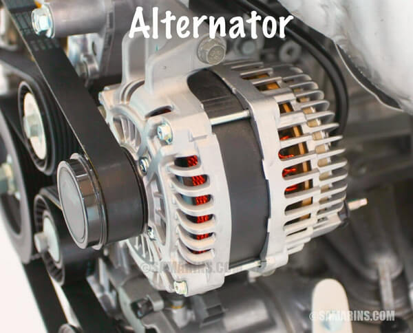
An alternator is a maintenance-free yet the most important unit of the car's engine. It generates electricity and functions to provide electrical supply to cars and recharges the battery. The alternator works by converting mechanical energy into electrical energy from alternating current to the direct current.
The primary function of an alternator is to work jointly with the battery to supply energy to the electrical components, i.e., lights, fan, windshield wipers, etc. It changes the alternating current into a direct current and regulates the voltage to meet the required minimum power for each unit.
The alternator comprises a cooling fan, voltage regulator, rotor, stator, diode bridge rectifier, slip rings, slip ring end bearings, carbon brushes, pulley. The rotor and stator are the central units for electricity generation, while the rectifier helps in converting AC to DC. All the components work jointly to monitor and regulate the power to match the energy needs of different components of the car's engine.
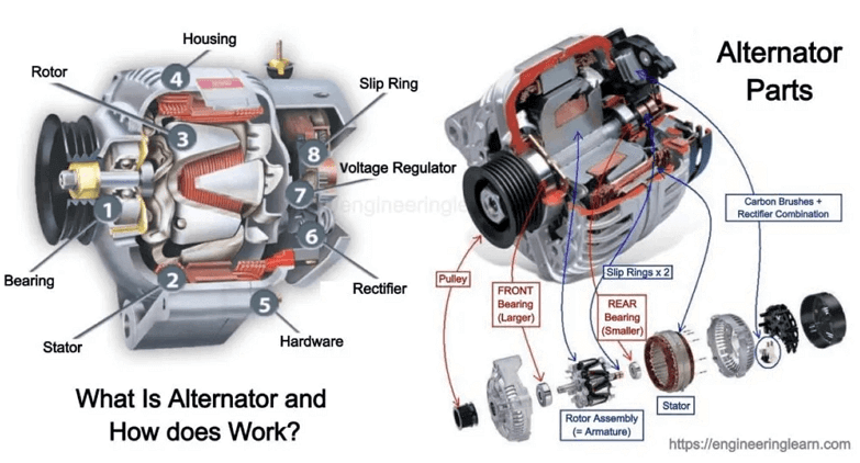
Image Source: Engineering Learn
How Does the Alternator Work?
The functioning of an alternator is straightforward. A serpentine belt that rests on a pulley is attached with an alternator. When the engine is ignited, the pulley moves and rotates the rotor shafts attached to the alternator. The rotor is an electromagnet with two revolving metal slip rings and carbon brushes attached to its shaft. Due to the rotation, a small amount of electricity is supplied to the rotor, which is conducted to the stator.
The magnets on the rotor are placed in such a way that they pass over the copper wire loops in the stator. This creates a magnetic field around the coils. When the rotor spins, the magnetic field is disturbed, and this, as a result, generates electricity.
However, the current generated is AC has to be converted to DC before use; therefore, it is channeled to the alternator's diode rectifier. The rectifier changes the two-way current into a one-way flow-direct current. The voltage then passes on to the voltage regulator that steps up or steps down the voltage to match the needs of different units of the car.


Alternator Wiring Diagrams
Below given are some alternator wiring diagrams that are used for different purposes. Let's have a look at their connections.
3 Wire Alternator Wiring Diagram
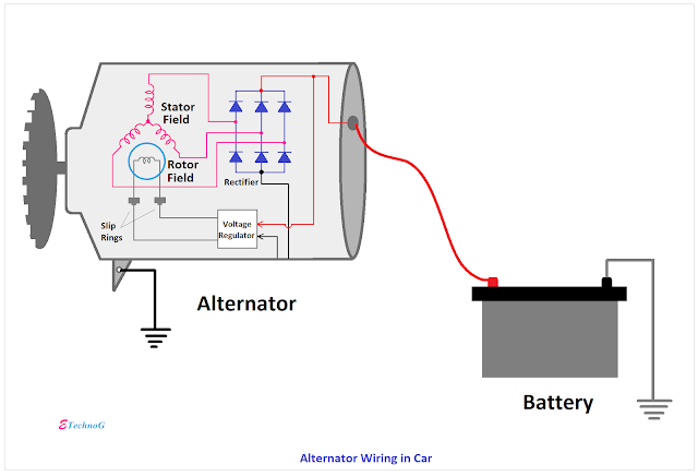
This is a three-wire alternating wiring diagram showing the connections between the different components of a circuit. The circuit comprises three main wires: battery positive cable, voltage sensing wire, and ignition wire. The ignition input wire is attached to the engine. It conducts electricity from the engine to the alternator while the voltage-detecting cable senses the voltage and is attached to the rectifier.
Such alternators are multi-purposed and have built-in voltage rectifiers for power sensing. Unlike the one-wire alternators, they can generate and rectify electricity in one circuit. Using a three-wire alternator ensures regulated voltage for all components.
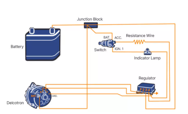
External Electromechanical Voltage Regulator
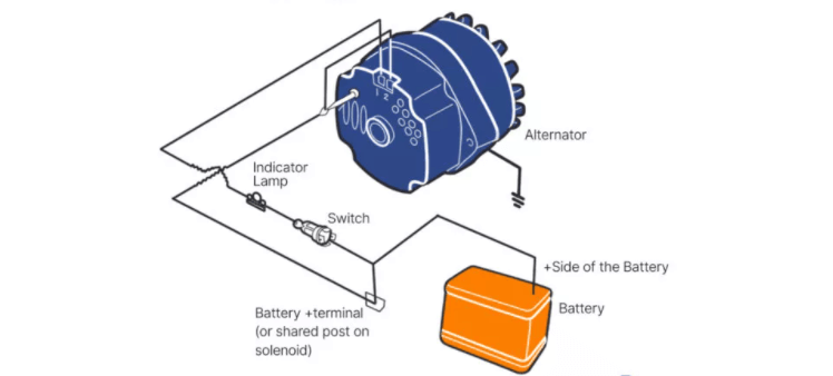
Electromechanical regulators coil the voltage sensing cable into an electromagnet. This creates a magnetic field around the magnet and attracts the ferrous block towards itself. Such circuits have three electromagnetic switches- cutout relays, regulator and, current regulator. The cutout relay connects the battery to the alternator while the regulator and current regulator switch regulate the voltage output by controlling the alternator's field circuit.
The electromechanical circuits are important for the AC stabilizing circuits; however, they are not used in production vehicles due to their inefficient relaying system.
PCM Controlled Wiring Diagram
The powertrain control module voltage regulation circuits are an advanced type of alternator that uses internal modules to control the field circuit of an alternator. The PCM regulates the current flow by examining the data from the body control module (BCM) and understanding the charging needs of a system.
Whenever the voltage is below the desired value, the modules are triggered, and it changes the on-time of current flow through the coil. As a result, the system output is changed to adjust the needs of the system. The PCR-controlled alternators are simple yet very efficient, generating the desired voltages.
Use EdrawMax for Wiring Diagram Creation
Alternators are very useful for keeping the car running when the engine is ignited. Alternators involve complex wiring, and the wires must be connected to the correct units and terminals. This can be simplified by creating alternator wiring diagrams.
Wiring diagrams provide a visual representation of the connections and physical layout of the circuit. With a clear visualization of each component’s wiring connections and position, it becomes easier to create circuits and connect the alternator correctly. Creating circuits with proper wiring is necessary to supply a proper voltage to each unit, so none gets over or underpowered.
Create wiring diagrams is simple and exciting if you have EdrawMax. EdrawMax is a user-friendly and innovative software that allows users to get creative and draw the most beautiful diagrams in just a few clicks. The software has a gamut of editing tools and a wide range of highly customizable symbol library that offers the freedom of creating whatever you want. Choose from the built-in templates or get innovative and design your own original diagrams from scratch. With an intuitive interface and extensive editing options, express your creativity and design helpful alternator wiring diagrams.
