Basic Electrical Symbols and Their Meanings
Do You Want to Make Your Circuit Diagram?
EdrawMax specializes in diagramming and visualizing. Learn from this Electrical Symbols complete guide to know everything about the Electrical Symbols and make Circuit Diagrams. Just try it free now!
Electrical symbols play a vital role in circuit diagrams. There are many standard symbols to represent specific components in a circuit diagram. EdrawMax will help you learn the usually used symbols for drawing circuits. Some electrical and electronic schematic symbols are used to signify electrical and electronic devices. When creating circuit diagrams, we primarily use these.
Here is the contents of this article, and you can click to learn what you want.
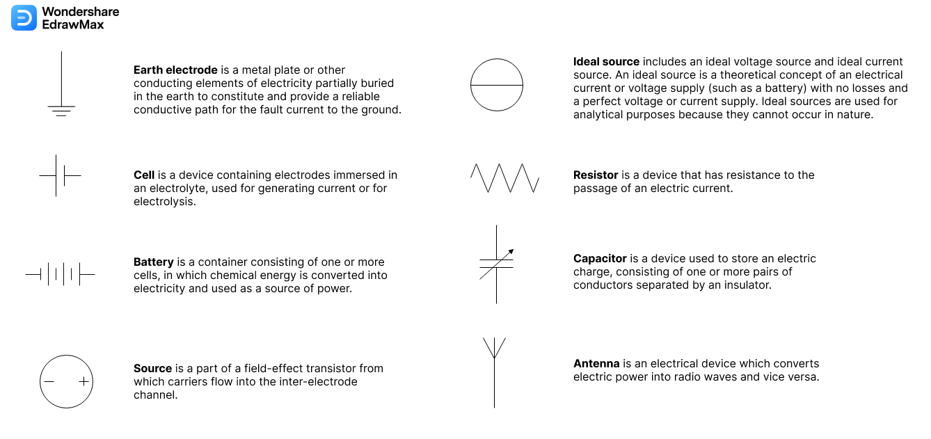
Part 1: Basic Electrical Symbols
Basic electrical symbols contain earth electrodes, cells, batteries, resistors, etc. Whether you are a novice or a professional engineer, these basic symbols can help create accurate electrical and circuit diagrams in minutes.
You can depict a complex electrical circuit with standard and simplified electrical symbols. Therefore, anyone who knows of electrical and electronic circuits can read, understand, and build electrical diagrams quickly. The symbols images are below.
- Earth electrode is a metal plate or other conducting elements of electricity partially buried in the earth to constitute and provide a reliable conductive path for the fault current to the ground.
- Cell is a device containing electrodes immersed in an electrolyte, used for generating current or for electrolysis.
- Battery is a container consisting of one or more cells, in which chemical energy is converted into electricity and used as a source of power.
- Source is a part of a field-effect transistor from which carriers flow into the inter-electrode channel.
- Ideal source includes an ideal voltage source and ideal current source. An ideal source is a theoretical concept of an electrical current or voltage supply (such as a battery) with no losses and a perfect voltage or current supply. Ideal sources are used for analytical purposes because they cannot occur in nature.
- A resistor is a device that has resistance to the passage of an electric current.
- A capacitor is a device used to store an electric charge, consisting of one or more pairs of conductors separated by an insulator.
- An antenna is an electrical device that converts electric power into radio waves and vice versa.
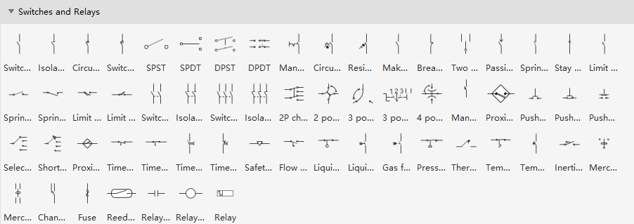
Symbols can be found in EdrawMax Symbol Library
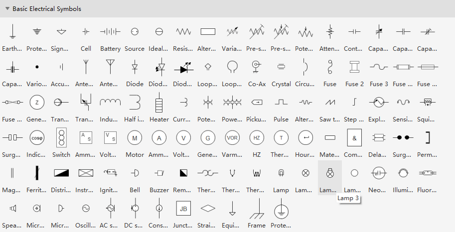
Some most commonly used basic electrical symbols in schematic diagrams are shown below:
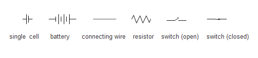
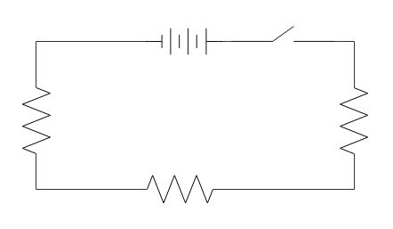
Example one: Three D-cells are placed in a battery pack to power a circuit containing three light bulbs. The resistor symbol represents each light bulb. The connecting lines are used to connect the symbols. At the same time, don't forget to put the switch in the circuit to control the current flow. The final sketch is shown in the following picture.

An all-in-one platform for 210+ diagrams.
・ Simple alternative to Visio
・ 26k+ symbols
・ 10K+ free templates
・ 10+ AI diagram generators


Part 2: Switches and Relays Symbols
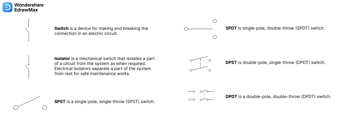
The picture below shows switch symbols. Switch 1P, isolator 1P, circuit breaker 1P, SPST, SPDT, DPST, DPDT, and more symbols are available in EdrawMax.
- Switch is a device for making and breaking the connection in an electric circuit.
- Isolator is a mechanical switch that isolates a part of a circuit from the system as when required. Electrical isolators separate a part of the system from rest for safe maintenance works.
- SPST is a single-pole, single-throw (SPST) switch.
- SPDT is a single-pole, double-throw (SPDT) switch.
- DPST is a double-pole, single-throw (DPDT) switch.
- DPDT is a double-pole, double-throw (DPDT) switch.
Symbols can be found in EdrawMax Symbol Library
As you can see from the above pictures, using electrical symbols to draw an electrical circuit diagram is quite easy. To illustrate the method, we will give you another example of using basic electrical symbols.
Example two: Three D-cells are placed in a battery pack to power a circuit containing three light bulbs. Firstly, quickly figure out which electrical symbol shall be used in the diagram. Then, think about the layout of these symbols. Last but not least, use a connector tool to connect all the electrical symbols.
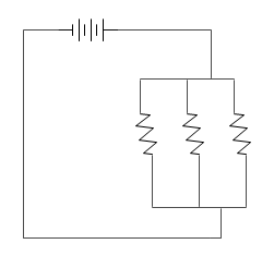
Using the basic electrical symbols to draw a circuit diagram can show the manners in which the circuit components are placed. With the complete electrical schematic, you can read the picture to know an electric circuit's physical connections and layout.
An all-in-one platform for 210+ diagrams.
・ Simple alternative to Visio
・ 26k+ symbols
・ 10K+ free templates
・ 10+ AI diagram generators
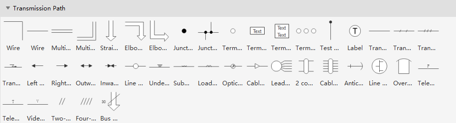
Part 3: Transmission Path Symbols
The basic electrical symbols are used to simplify the drafting and to help people understand the electrical drawing. Electrical symbols are standardized throughout the industry, so it is easy to achieve the ability to interpret the meaning of the symbols. With the standard electrical symbols in Edraw, you can create a circuit diagram that shows the actual layout of the components simply and quickly. The symbols images are below.
- Wire is used to connect the components in a circuit.
- A test point is a location within an electronic circuit used to either monitor the state of the circuitry or inject test signals.
- Outward flow means flowing outwardly.
- Inward flow means flowing inwardly.
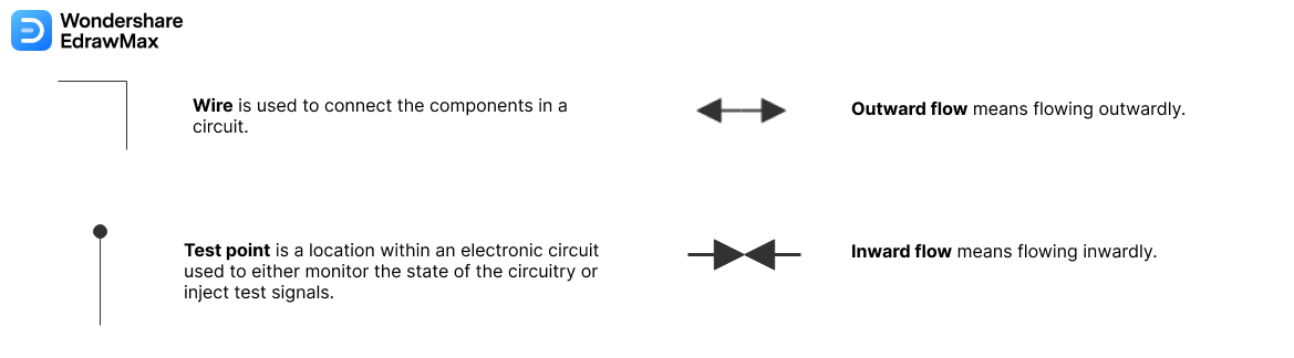
The picture below shows the transmission path symbols like wire, multi-line bus, straight bus, junction, terminal, test point, label, outward flow, inward flow, etc.
Symbols can be found in EdrawMax Symbol Library
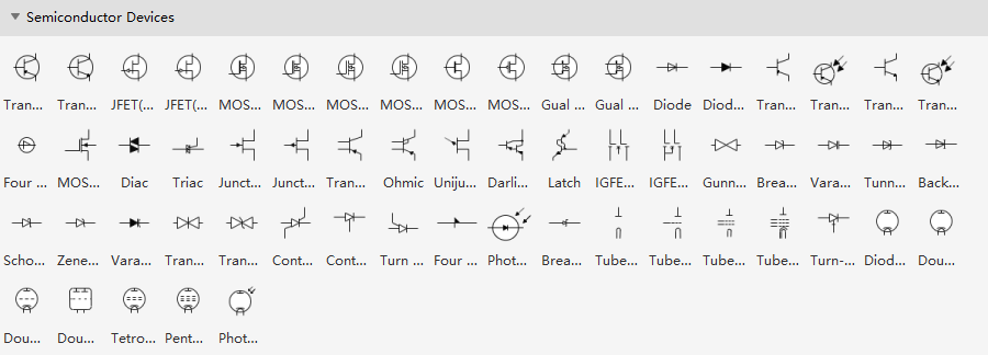
Part 4: Semiconductor Devices
The image below is about the semiconductor devices.
- Transistor PNP is a semiconductor device provided with three terminals called base, emitter, and collector, which allows current flow when the low potential at the base (middle).
- Transistor NPN allows current flow when high potential at the base (middle).
- Diode is a semiconductor device that allows the current to flow in one direction only.
- The electrical properties of a Tube are not substantially modified by the ionization of residual gas or vapor when there applies a high pressure.
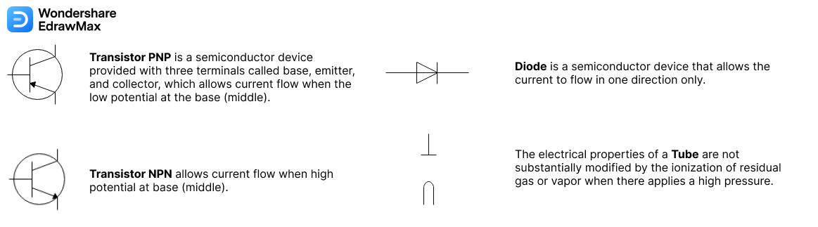
Symbols can be found in EdrawMax Symbol Library
Part 5: How to Create a Circuit Diagram with Electrical Symbols
It is easy to create an electrical diagram when you know where to find thousands of electrical symbols. Watch the video below and learn how to create an electrical circuit diagram. Alternatively, you can follow the instructions for words and pictures step by step.


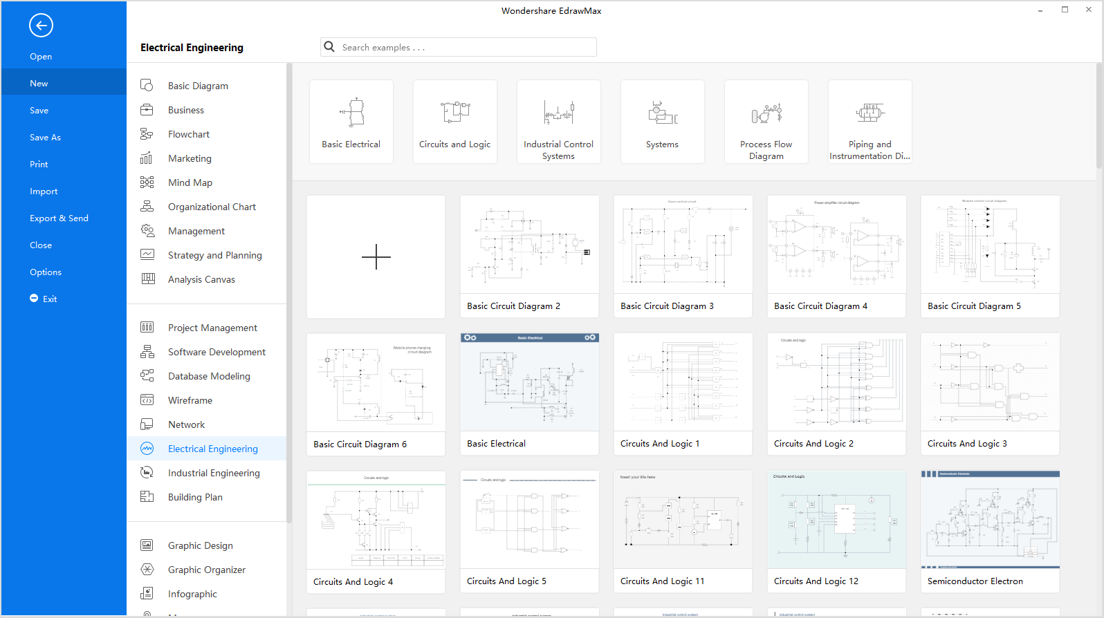
Step 1: Launch EdrawMax on your computer. An extensive collection of electrical diagram templates can be found in the Electrical Engineering category. Click the icon of Basic Electrical to open the library that includes all symbols for making electrical diagrams.
Step 2.1: As you are into the workspace of EdrawMax, drag the symbol that you need directly onto the canvas. You can resize the selected symbol by dragging the selection handles. A double-sided arrow shows the direction to which you can move the mouse, and you can only move the symbol when a four-direction arrow appears.
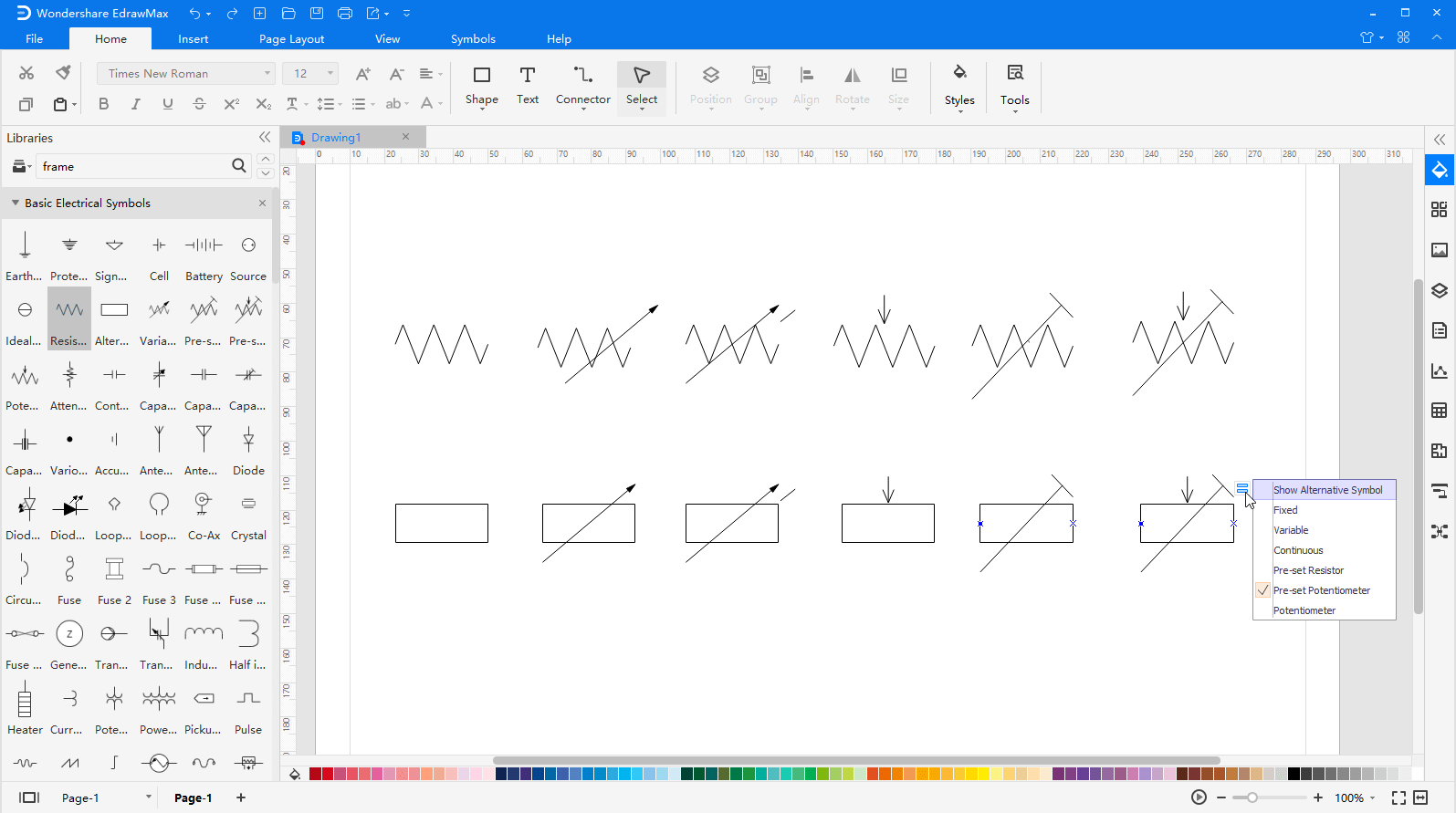
Step 2.2: You can also change the shape of the symbol via the floating menu/action button. It shows when the symbol is selected or when the pointer is over the symbol. For example, the resistor can have 12 kinds of variations.
Step 3: When your electrical diagram is complete, you can export it to JPG, PNG, SVG, PDF, Microsoft Word, Excel, PowerPoint, Visio, and HTML with just a single click. So you can share your drawings with people who don't use EdrawMax with no need to look for ways of converting file formats.

More Related Articles


