UML Diagram Examples
To efficiently create UML diagrams, it is better to start from editable UML diagram examples. Here present 14 types of UML diagram examples for helping you create UML diagrams, even without drawing skills. All examples are available in vector format and free to download.
UML Diagram Types
The UML diagram falls into two categories.
- Structural Diagram
- Behavioral Diagram
Structural UML Diagram
The structural UML diagram shows us the basic structure of the software system. Like how are the classes and other primary components are connected? The structural diagram illustrates the relationship between the classes, objects, packages or modules, physical nodes, components, and interfaces.
This is like the architectural design of the building. We see that there are walls, windows, doors, electrical components, plumbing, etc., in the design same goes with the structural UML diagram. It is also the architecture of the house.
There are seven types of the Structural UML diagram. And they are as follows.
- Class Diagram
- Component Diagram
- Deployment Diagram
- Object Diagram
- Profile Diagram
- Package Diagram
- Composite Structure Diagram
Behavioral UML Diagram
The behavioral UML diagram illustrates the dynamic activity of the classes, objects, packages or modules, physical nodes, components, and interfaces. It shows us how the classes, objects work, what a function does inside a class. How are the functions connecting different classes dynamically?
The communication of objects, The movement of the data caused by the functions, objects, etc. In what way the classes and their components are changing with time. What special event is causing the behavior? What will happen, or what will be the output of the user’s input. In short, the behavioral UML diagram shows us the motion of the classes. The seven types of behavioral UML diagrams are.
- Use Case Diagram
- Activity Diagram
- State Machine Diagram
- Sequence Diagram
- Communication Diagram
- Interaction Overview Diagram
- Timing Diagram
UML Diagram Examples
Class Diagram Examples
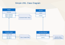
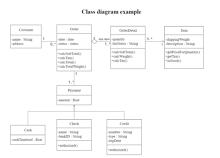
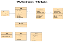
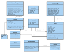
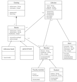
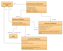
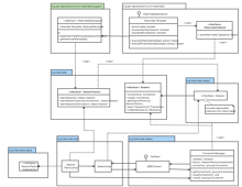
In the class diagram, we learn about the classes, their properties, methods, and constructors. The class diagram also tells us about the relationship between different classes when the classes in the project become so complex to understand.
The above diagram is the class diagram. The square shape container is the class, and inside these classes, there are properties, constructors, and methods. The class name is always written on the above. The properties or attributes are written in between, and in the last, the methods come. We also see the relationship between these classes. These classes are having an aggregate relation with each other.
Component Diagram Examples
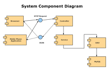
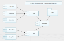
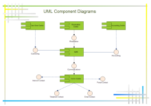
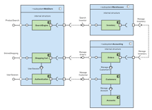
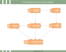
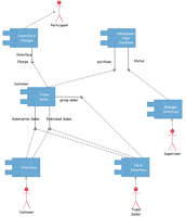
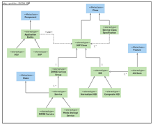
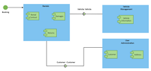
The UML Component Diagram shows the components and their relation in the complex software architecture with dozens or more components. When there are so many software components, a separate UML is designed for them, and it is the UML Component Diagram. The components are related to each other through the interfaces.
Deployment Diagram Examples
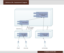
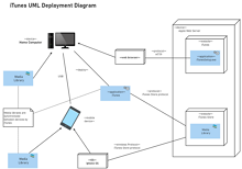
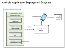
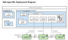
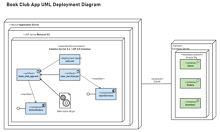
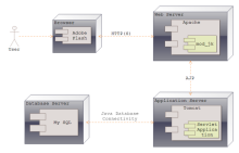
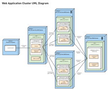
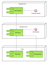
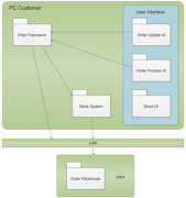
The Deployment Diagram shows us the hardware components of the machines, and inside the hardware, the softwares are placed. It is used when the software is deployed on multiple machines, software components, and each machine has different hardware specifications.
Object Diagram Examples
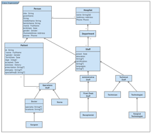
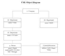
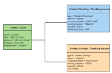
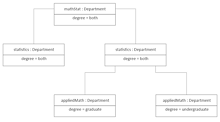
The Object Diagram is the mirror of the class diagram. But it has the difference that the object or instance diagram shows us the relationship between different objects. When there are thousands of objects in software so, there is a need to draw them in a separate chart, and this diagram is known as the object diagram.
Profile Diagram Examples
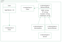
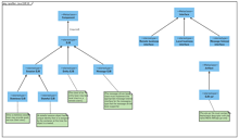
The profile diagram, in simple words, is the extension of the traditional UML diagram. This diagram introduces the concepts like:
- Stereotypes: make your diagram more clear; when you have to make a new feature from the existing feature, then you can use it.
- Tagged Values: simply add the information on the classes.
- Constraints: are some conditions that have to meet to do some work.
Package Diagram Examples
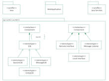
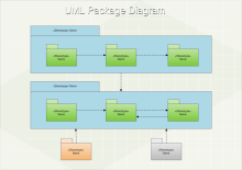
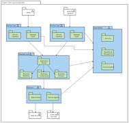
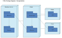
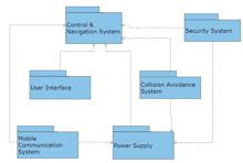
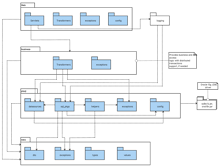
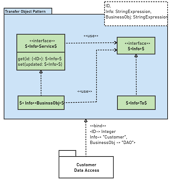
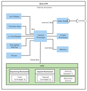
The UML Package Diagram shows us the relationship between different packages, and inside these packages, there are some functionalities that other classes or packages use to do their work.
Composite Structure Diagram Examples
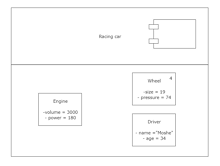
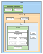
The Composite Structure Diagram is an internal diagram that shows us the internal structure of a particular class. Not only the internal structure, but it also shows the properties and methods collaborating with other class’s properties and functions. Like if class one uses port 8000, then how the other class uses the same port to interact with the functionality of the other.
Use Case Diagram Examples
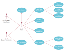
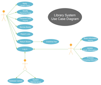
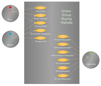
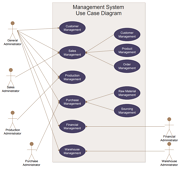
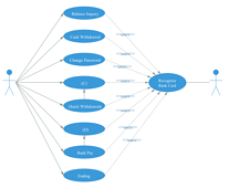
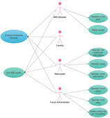
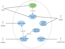
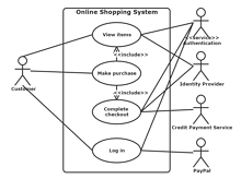
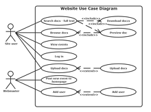
When a person interacts with the user with his problem, see, it will make a case. The Use Case Diagram is also a type of Behavioral diagram that shows us the possible use cases of the system and the user. In a Use case diagram, there are multiple possible use cases, and there is a user too, and those use cases interact with each other based on user input.
Activity Diagram Examples
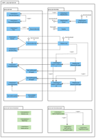
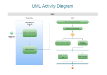
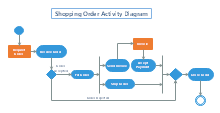
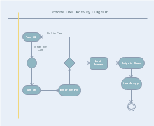
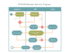
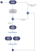
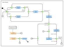
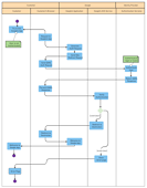
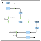
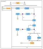
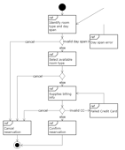
The Activity Diagram shows us the activity of different components step by step and how are these activities communicate with other activities to produce some results.
State Machine Diagram Examples
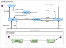
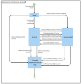
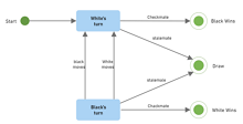
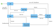
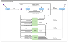
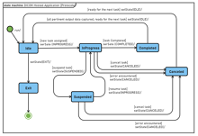
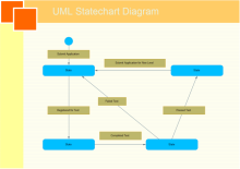
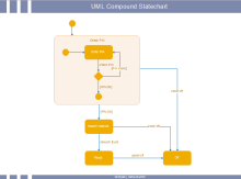
The UML State Machine Diagram is a behavioral diagram that tells us about the different states of machines. Depending on a state, how the system or object behaves. You are allowed to use a state machine diagram for any object and for any other element that performs some actions.
Sequence Diagram Examples
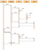
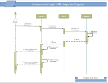
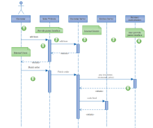
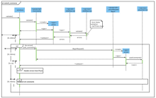
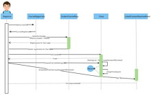
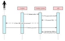
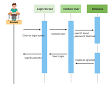
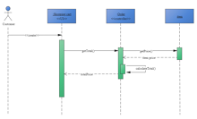
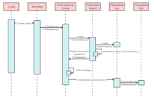
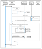
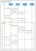
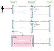
The Sequence Diagram shows us the objects and their interaction in the correct sequence order. We can also say it like the event. When a particular event occurs, a particular object will work, and these events occur in sequential form.
Communication Diagram Examples
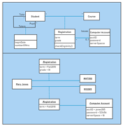
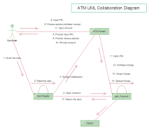
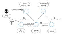
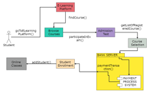
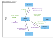
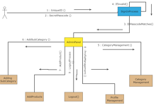
The Communication Diagram is the extension of the object diagram that tells us about the communication of objects with each other. How the objects are sharing data and overlapping and all these things we get from the communication diagram.
Interaction Overview Diagram Examples
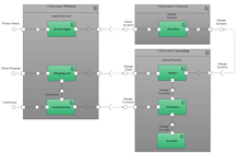
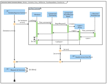
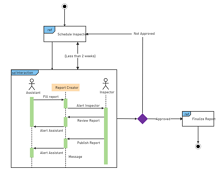
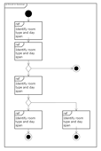
The Interaction Overview Diagram is an interaction or communication UML diagram that tells us about the control flow plus classes or nodes in the same diagram. It focuses on those nodes or classes that are interacting with each other.
Timing Diagram Examples
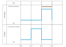
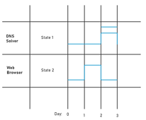
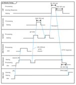
The Timing Diagram shows the occurrence and changing of time along a linear axis. It tells both classifiers and their interactions concerning the time.
Benefits Of Using UML Diagram
The UML, abbreviated to Unified Modeling Language, is a general way of describing how the system structure would work, how it would work, how the object is connected, and the relationship between the objects.
The Unified Modeling Language is used in software development. The diagram is drawn before the software developers or engineers start to code the system. To understand the UML, you should know Object-Oriented-Programming because it is the root cause of developing a UML diagram.
To understand the UML, it’s good practice to know the Object-Oriented-Programming(OOPS). In computer science, the OOPS and the UML are studied together. In OOPs, we have classes that are simply the data structures containing objects, properties, methods, and other functionalities. When we make many classes, understanding their functionality and the relationship between them becomes very complex. So, the UML diagram provides us all the functions to depict what the class does. Their relation is drawn with the arrow line. The classes are drawn with the square box. Inside the box, we define constructors that initialize and instantiate the objects, properties, and private, public, protected, or static methods.
Therefore, when you develop and use a UML diagram, you will:
- Get a visual representation of how your software or system would work after developing.
- Get a better understanding, and it will help you in debugging.
- The formal relationship between the elements is shown.
- The UML is a planning tool it will help you in extending your system without any confusion.
Use EdrawMax for UML Diagram Creation
EdrawMax is a diagram-making software that can help you make 280+ types of diagrams easily and efficiently. The software contains all the necessary tools and features that will suffice you in your diagram making. All the pre-made diagram examples and symbols easy to use and customize in EdrawMax, thus you can create high-quality UML diagrams without drawing skills.
