P&ID are a low-costing yet useful way of illustrating working models and systems. These diagrams assist in planning the process, flow, and working of the model. Microsft Visio is one of the diagramming software used to create Piping and instrumentation diagram that ensures high planning security with ruled-based work with uniqueness in the symbol numbering.
Read on to learn how to make a P&ID in Visio. Also, learn about EdrawMax, a better alternative for Visio.
How to Make a P&ID in Visio?
Creating a P&ID with Visio is super easy. Follow these steps to begin.
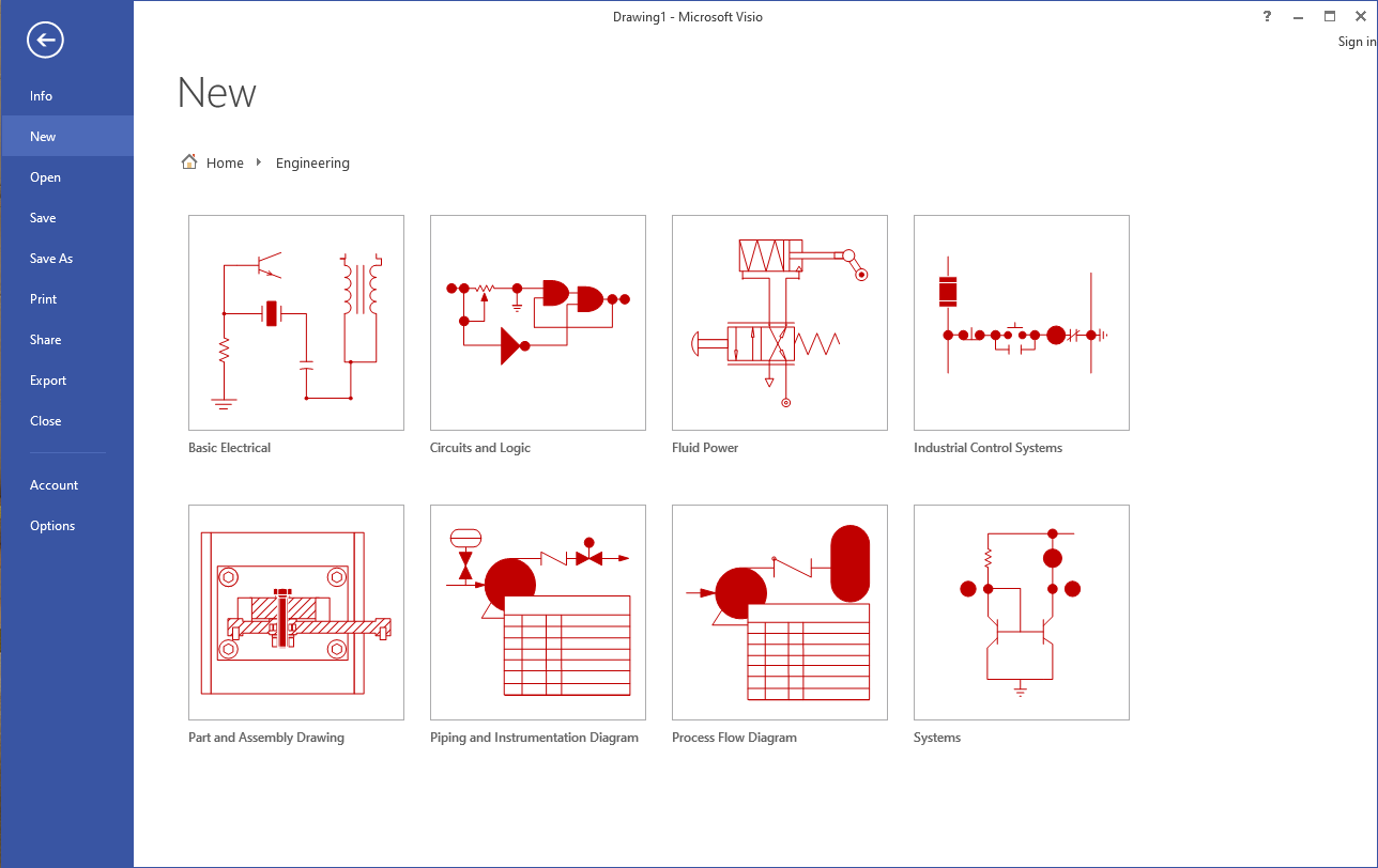
Step 1: Launch Microsoft Visio on your PC. Select any of the two following templates and click Create.
- Piping and Instrumentation Diagram
- Process Flow Diagram
Step 2: Different shapes are present in the panel on the right side. Search and select shapes from the equipment category and drop them onto the drawing page. Next, fill in the pipelines to connect all the equipment. From the pipelines category, select the pipe and position its one end on equipment. Drag the other endpoint to join with the other equipment. The endpoint will turn green to indicate a connection has been made between the two equipment.
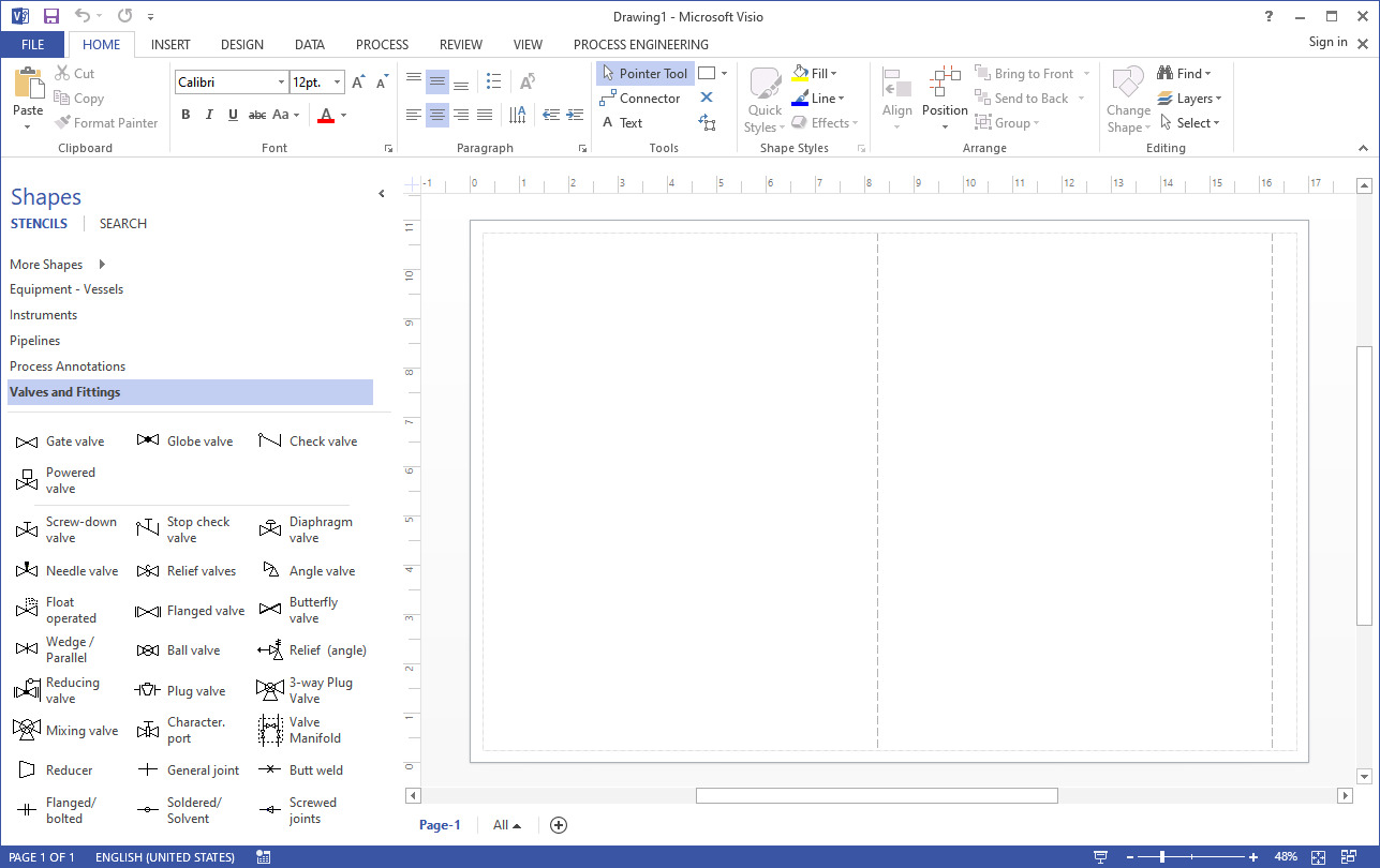
Step 3: Select the Valves & Filling category to introduce valves in your pipes. Drag the desired valve on the pipe and release the mouse click when the green square appears. This indicates that the valve has been fitted into the pipeline. From the Instruments category, insert the shapes in your diagram near the valves, pipelines, or any equipment they are associated with. Resize and reposition the shapes to adjust to your diagram.
Step 4: To add data to your components, hover your mouse to the Data tab and click Shape Data Window. On the drawing page, select the shape you want to add the data and type in or select a value. You can renumber components, generate reports, create and apply property sets and do much more. After you are done, save your work by going to the File tab and click Save.
How to Find More Engineering Shapes in Visio?
Shapes are the functional pillar of a P&ID. Read on to learn two ways of getting the shape that fits your diagram perfectly.
Use The Search Box
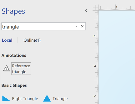
Enter the name/keyword for the equipment in the search box located at the top of the shape pane.
- The Local category includes the Visio in-built shapes arranged by their Visio stencil title.
-
The Online category includes shapes created by different companies that are available on the web. To add the shapes in your folder, do the following:
- Click on the stencil to preview.
- Click on Download to add it to the My Shapes folder.
-
After downloading, click Open to find the stencil in the shape pane.
Find Shapes Online
With access to the internet, you can also view and download shapes created by people outside Microsoft. The shapes can be downloaded from:
- New Microsoft Office Shapes
- Network Equipment Shapes
- Azure Cloud and Al Shapes
How to Make a P&ID in EdrawMax
EdrawMax is a diagram illustration software that allows its users to create P&IDs effortlessly. You can download and customize 100+ P&ID templates and examples that are made by our professional designers. (Find more templates from our user-generated template community) In addition, EdrawMax also provides the standard P&ID symbols to help you create any type of P&ID from scratch. Here are the steps to create a perfect P&ID with EdrawMax.
1, Launch EdrawMax on your PC and tap New.

2, Select Industrial Engineering from the options in the right pane and click on the Piping & Instrumentation Diagram. Click on the ‘+’ shaped icon to start from scratch or load a pre-made template.
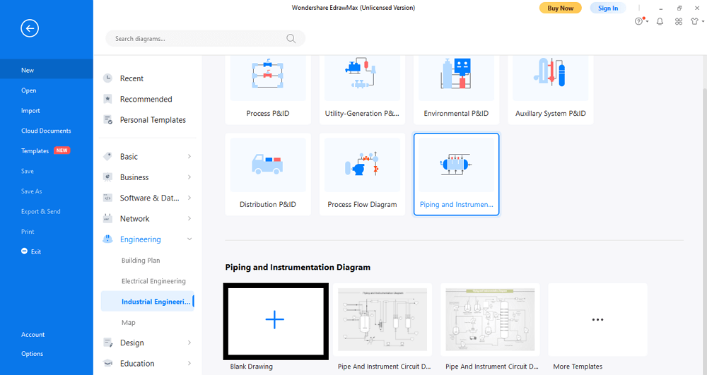
3, The symbol library appears on the right side of the screen with instruments categorized based on their use. From the Equipment tab, drag the desired symbol shapes on the screen.
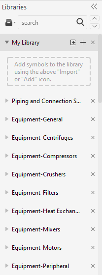
4, Next, connect your symbols with connection lines. Under the Piping and Connection symbols in the library, select the different line types and resize them to connect with different equipment. You can also introduce valves and instruments likewise.
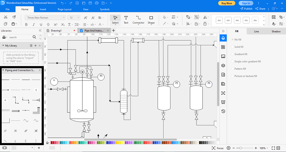
5, Double Click on the shape to add data.
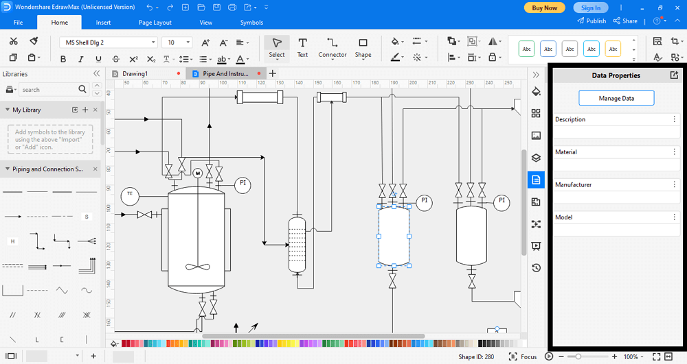
6, After you are done, click on File followed by Save. Browse the destination for your work and tap Save.
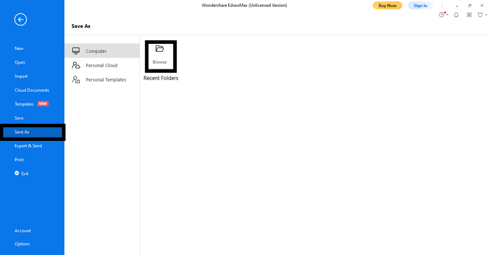
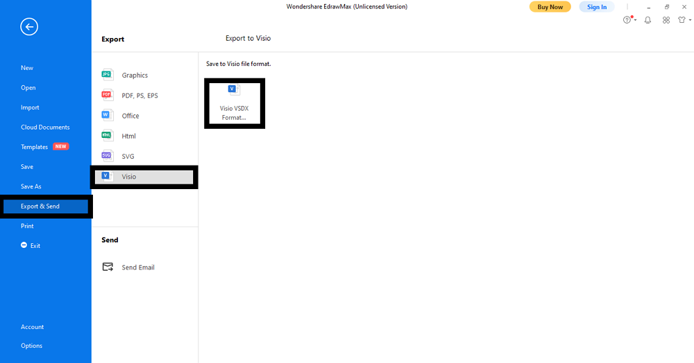
7, Most importantly, if you want to save your file as a Visio document, just go to the File tab and select Export & Send. Select Visio > Visio VSDX format to save the illustration in Visio format. Here you can get a Visio P&ID file without diagramming on Visio.
Use EdrawMax for P&ID Creation
It’s a Wrap-Up! Piping and Instrumentation diagrams are a practical way of displaying construction and building models. It becomes easier to explain even the most complex diagrams effortlessly with properly assigned symbols and piping lines. P&ID’s are extensively used by engineers, and with EdrawMax at disposal, creating them is just a five-finger thing.
EdrawMax is user-friendly software with an intuitive interface that offers a list of features for illustrating different types of diagrams. The software has a gigantic library of highly customizable symbols and a massive range of editing tools to help create the diagrams effortlessly. Besides, it allows users to create diagrams from scratch or with pre-made templates. In short, EdrawMax is the professional solution to all your illustration problems.
