Logical Network Diagram Complete Guide
Edraw Content Team
Do You Want to Make Your Logical Network Diagram?
EdrawMax specializes in diagramming and visualizing. Learn from this logical network diagram complete guide to know everything about the logical network diagram. Just try it free now!
Understanding the importance of a logical network diagram in telecommunication is very imperative. It helps in managing network and information technology infrastructure efficiently. Network diagrams comprise physical and logical network diagrams.
The logical network diagrams expound on the logical components of computing devices within a network, including hardware and cables. Like a floor plan, it displays the physical structure or layout of a network. This Logical Network diagram complete guide covers numerous subjects such as physical network diagram, network topology, and the several types of topologies. In addition, the article will explore how you can use EdrawMax software to create simple and complex logical network diagrams.
1. What is a Logical Network Diagram
A logical network shows a part of a physical network connecting several logical network devices or interfaces. Unlike a physical network, a logical network cuts across several physical devices. Networking equipment and network nodes are part of a separate physical network. For instance, a logical network can comprise elements from different networks with devices located worldwide.
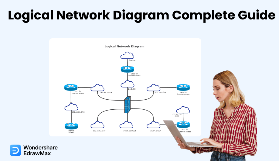
A logical network diagram shows how data and information flow in a network. In a logical network diagram, you can see elements such as routing domains, network objects (firewalls and routers), subnets (VLAND IDs, IP addresses, subnet mask), voice gateways, and specific routing protocols, network segments, and traffic flow.
Since information and data contained in logical network diagrams correspond to the layer of the OSI model, L2 devices are not represented in a logical network diagram. Although physical network diagrams are essential, logical network diagrams have several uses. The following are a few reasons why the use of a network diagram.
Firstly, using a logical network diagram makes it possible to ensure your firewall rule bases remain accurate. Secondly, it is easier to identify an issue, especially if the service is off between two IP addresses. You can pinpoint the firewall causing the problem with a logical network diagram. Moreover, a logical network diagram not only allows you to conceal physical information regarding a network even though you decide to share the information but also to map out or change the network and see the impact.
2. What is Logical Topology
A network topology represents the arrangement of different components in a network. It describes both the logical and physical aspects of a network. A logical network topology can be dynamically reconfigured and maintained using networking equipment such as switches and routers.
Since it illustrates network devices communicate with one another, logical topology comprises three types: bus topology, ring topology, and mesh topology. Let us look at these different logical topologies briefly.
2.1 Bus Topology
Among the several types of logical network topology, bus topology is the simplest channel or bus used for network communication. It is usually connected to several droplines and taps. If you are new to topology, droplines are the cables that connect the bus to your computer, whereas taps are the connectors. Therefore, you will only see a single transmission line for all the nodes in a bus topology. You can see a bus topology as a speaker in a conference call. Whatever the speaker speaks, everyone connected to the call receives the information. Likewise, once a sender sends a message in a bus topology, all computers connected to the topology can hear the message. However, the receiver can only accept the message. In most situations, bus topology is suited for a small network such as a local area network (LAN). In the bus topology, the bus functions as the network backbone that connects every peripheral and computer in the network. Both shared channel ends have line terminators. Therefore, the data can only be sent in one direction. In addition, once the data reaches the end, the terminators eliminate it from the communication route to avoid data flow disruption and the signal from bouncing. Furthermore, every computer communicates with each other independently in a bus topology. Therefore, each computer and peripherals can access and share the network capabilities. Therefore, the connected devices share responsibility for data flow from one point to another within the network.
Advantages of Bus Topology:
-
It is cost-efficient to implement.
-
It it easy to install and use.
-
It does not require much cabling.
-
The failure of one node does not affect the other nodes.
Disadvantages of Bus Topology:
-
Traffic and congestion affect the network.
-
Security issues as messages are sent to all nodes.
-
There is a limited number of nodes to be connected.
-
The failure of the bus affects the entire network.
-
It is less efficient with more nodes connected.
2.2 Ring Topology
While the bus topology has a few drawbacks, the ring topology leverages some drawbacks. It allows each computer to connect to another network, forming a ring. Unlike the bus topology, the message passes in a circular and unidirectional manner in the ring topology. The network is deterministic since every computer has access to transmit messages at a given time interval. The nodes are connected in a closed-loop nature and work on a token-based system, with the token traveling in a particular direction. Peradventure, a token is unrestricted. The node can capture the token and attach the token's data and destination address before leaving the token for communication. Once the token gets to the destination node, the receiver removes the data, allowing the token to transfer the next data.
Advantages of Ring Topology:
-
Every node receives the same access time.
-
It requires less cabling.
-
It has easy installation process.
-
It minimizes the likelihood of data collision .
-
It is easy to troubleshoot.
Disadvantages of Ring Topology:
-
It's hard to reconfigure.
-
Once a particular node fails, the entire network fails.
-
The data transmission speed is slow.
2.3 Mesh Topology
Lastly, the mesh topology represents a network where each node is connected. Therefore, every node has direct communication with each other within the network. Mesh topology is divided into two types - partial and full mesh. In the partial mesh, nodes are not connected, whereas each node is connected to others in a full mesh. This is because it uses a point-to-point connection between all devices in the network. Because of this, it has a prominent level of redundancy.
Advantages of Mesh Topology:
-
It offers fast communication.
-
There is no traffic or congestion issue with the channels.
-
If a particular node fails, there are alternative nodes available.
-
It has good fault tolerance and dedicate links that help to offer direct communication.
-
It maintains security and privacy because of a separate communication channel.
Disadvantages of Mesh Topology:
-
It has complicated installation and maintenance process.
-
It's cost-inefficient and too complexto implement.
-
It requires high cabling .
3. Differences between Physical and Logical Network Diagram
A physical network diagram describes a network topology, including switches, workstations, servers, and lines that connect these components. It illustrates how data is transferred from one place to another inside a network. It does not have to resemble the physical arrangement in any way. Physical diagrams are Level 1 in the OSI networking framework (L1). Therefore, a physical network diagram can be a server, cabling diagram, rack diagram, etc., enabling everyone to view what it looks like.
On the other hand, a logical network diagram depicts how data connections function through computer networks. It also demonstrates how devices communicate with one another. While this logical network diagram may contain nodes comparable to those in a physical network diagram, the logical diagram uses lines that indicate data movement rather than a physical cable. Physical drawings cannot replace logical network diagrams for understanding the overall layout of a network and identifying specific pieces of equipment. Even with labels and arrows, it will be difficult to detect certain information about a network connection, such as what type of transmission media is utilized or if there are any electrical wiring difficulties.
An administrator can design logical network diagrams such as maps to illustrate their Cisco, WAN, LAN, AWS, etc. These diagrams depict the network in-depth or at a prominent level. As a result, admins can comprehend Physical and Logical network layout and functionality since the Physical and Logical network diagram shows all necessary data. Furthermore, it is easier to identify and handle problems quickly. Below you can see the difference between the logical and physical network diagram.
Physical Network Diagram:
-
It displays connected cables and physical devices.
-
Uses lines to show how the cables connect to every device.
-
It displays network elements like network segments, subnets, traffic flow, a network object, voice gateway, and routing protocols.
Logical Network Diagram:
-
It displays how data works and the information flow among networks.
-
Lines clarify how information flows within different devices in the network.
-
It displays network components, including ports, workstations, cables, servers, etc.
4. What's in Logical Network Diagrams
Logical network diagrams are used to show how computers and devices such as modems, printers, and switches are connected in a network. These electronic components comprise the physical network that provides a wide area network (WAN) and local area network (LAN) . The Internet can also be connected to a physical network in a specific location, allowing all connected devices to access the Internet.
A logical network diagram depicts how things work rather than how they are connected. Compared to physical network diagrams, logical network diagrams are more valuable. This style of diagram displays the connections between network components and provides information about these devices and how they perform in the bigger picture. On the Internet, you may find a variety of software packages for creating network diagrams.
Since a logical network diagram represents how information flows in a network, it comprises several components such as network objects (firewalls and routers), subnets, network segments, voice gateways, routing domains, and traffic flow. Therefore, several symbols are used in a logical network diagram, including printer, internet cloud, hub, bridge, router, and firewall.
5. How to Draw a Logical Network Diagram in EdrawMax
EdrawMax is a simple, all-around diagram tool that allows you to create network diagrams and other types of diagrams without stress. It contains symbols such as mainframe, terminal, cloud, firewall, comm-link, printer, switch, server, router, bridge, and hub. Logical network diagrams comprise symbols that make visualizing several types of networks easier. There are several ways to draw a logical network diagram. However, the best method is to use EdrawMax. It is an automated software that allows you to create a unique logical network diagram in minutes.
Step1 Open EdrawMax and Login
The very first step that you need to follow is to install EdrawMax in your system. Go to EdrawMax Download and download the network diagram software depending upon your operating system. If you need remote collaboration with your office team, head to EdrawMax Online and log in using your registered email address.
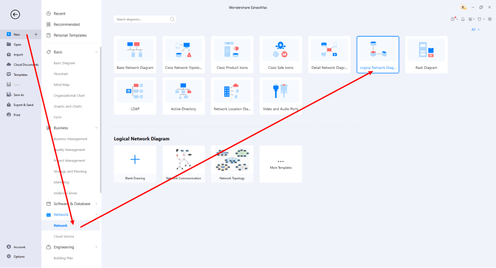
Step2 Select a Template
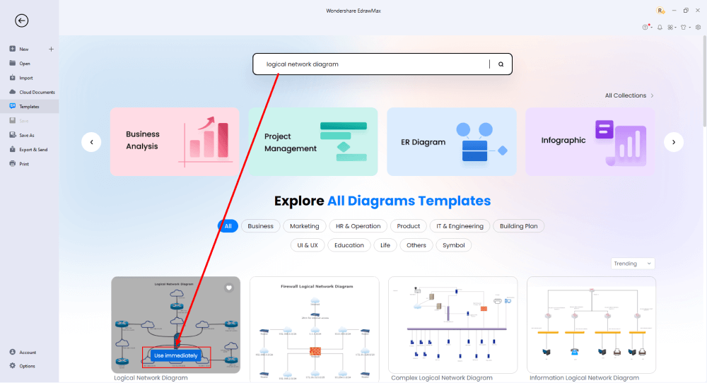
After launching, the Home screen opens by default. Head to the Template bar and search for Network Diagrams in the search box. In-built templates specific to your search will appear on the screen. EdrawMax features a large library of templates. We have more than 25 million registered users who have produced thorough Templates Community for each design. Select the template you like and click Use Immediately to open it in a new window for customization.
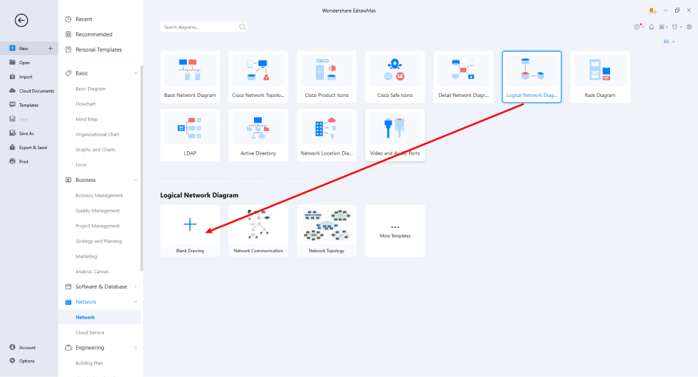
Step3 Create From Scratch
From the EdrawMax homepage, you will find the '+' sign that takes you right to the canvas board, from where you can start designing the network diagram from scratch. Coupled with your technical expertise, you can use a wide range of symbols to draw a detailed logical network diagram.
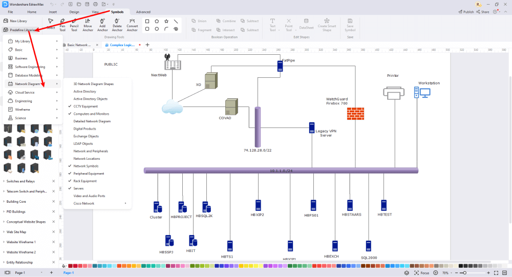
Step4 Select Symbols
EdrawMax includes a large number of symbol libraries. You may quickly build any type of diagram with over 26,000 vector-enabled symbols. If you can't locate the symbols you need, you can easily import some images/icons or build your own shape and save it as a symbol for later use. Simply go to the 'Symbols' part of EdrawMax and select the 'Predefined Symbol' section from the top toolbar. Hundreds of symbol categories are accessible for you to utilize and incorporate into your logical network diagram.
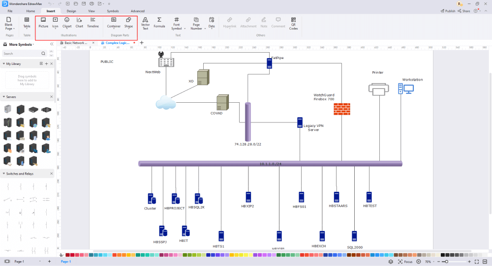
Step5 Add Components
After you have sketched out the basic pieces, you may customize the typefaces, colors, and other details by selecting the right or top menu to make your logical network design more visually appealing. Also, feel free to draw ideas from other layouts on Templates Community and transfer some of the photos or features that you think would go well with your logical network design.
Step6 Finalizing the Plan
Once your logical network diagram is ready, you can collaborate with your team to consider their opinion using the Cloud-base files. EdrawMax allows up to 100M free cloud storage. It supports files in several formats, including HTML, PDF, Graphics, Visio, Microsoft Office, etc. It is not a complicated process to create a logical network diagram in EdrawMax. You can take a template and continue customizing it to suit whatever design you want. EdrawMax has several templates with fantastic designs for a logical network diagram for your organization.

Basically, it is simple to create a logical network diagram in EdrawMax, just grab a template and keep customizing, drag and drop professinal symbols to make your plan better. If you are still confusing about how to make a logical network diagram in EdrawMax, just check this Logical Network Diagram Guide, or check the video below. Or you can find more tutorial videos from our Youtube
6. Logical Network Diagram Examples
EdrawMax offers you logical network diagram examples and templates. Depending on what you want, you can find logical network topology templates, including bus topology, ring topology, and mesh topology. Just click the image to download EdrawMax, and download the templates accordingly. Then double click to open the templates and customize as your prefer. Or open the templates from EdrawMax Templates Community, and duplicate the templates.
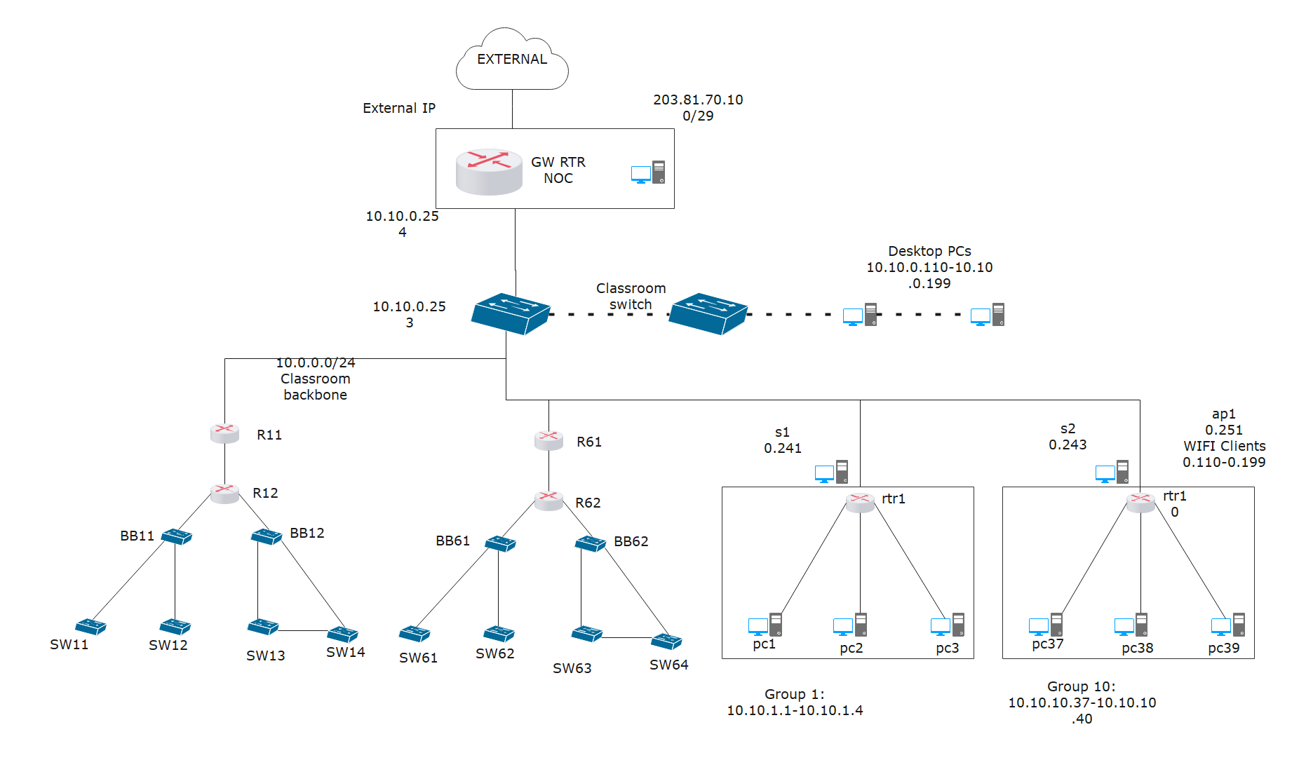
Example 1: Logical Topology Diagram
Above is a logical topology diagram example that displays a classroom setup. Because of the online classes' popularity contributed to administrators creating complicated setups. The setup above shows a central external IP with several desktops' computers connected to it. Note that the design can contain several routing domains or routers with numerous switches. The diagram showcases the relationship between different elements in the logical network.
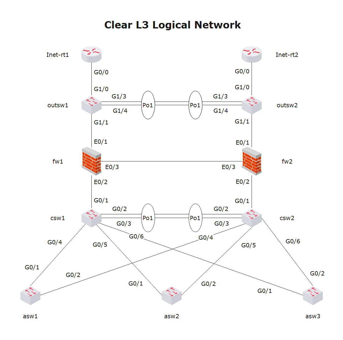
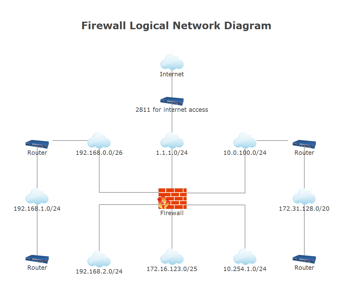
Example 2: Logical Network Design
The diagram above represents a logical network design, showing how data flow in a network. The components in the diagram include routing domains, traffic flow, subnets, firewalls, and routers.
Example 3: Logical Network Layout
The image above exemplifies a logical network layout for a server and firewall. It represents data flow in a network. The diagram shows some components, such as routing domains, traffic flow, routers, firewalls, and subnets.
7. Free Logical Network Diagram Software
Previously, network engineers had to build network diagrams manually. In most cases, these engineers use Visio before redrawing them. This would suddenly become a challenging process in an extensive or dynamic network. Today's network diagramming software automates creating and updating network diagrams while giving real-time network insight to aid troubleshooting. Try EdrawMax if you want an effective and user-friendly solution for automating your network diagram. It has a simple interface and a short process to make, allowing you to map diagrams. First, create the network diagram you require, including logical connections such as a switch to switch, node to node, and router to router port connections.
Below are EdrawMax's comprehensive features that will offer you an excellent drawing experience:
- Vector-based shapes and templates that are pre-designed.
- An all-in-one diagram maker that can make over 280 types of diagrams and serve all of your purposes.
- Run on common operating systems(Win, Mac and Linux) and work on different devices.
- Seamlessly integrated with MS Office Suite.
- Export documents into various file formats and has great compatibility.
- The user interface is simple to use, so even a novice can locate what they are looking for.
8. Final Thoughts
A logical network diagram visually represents a department, team, or company's network topology. It depicts the relationship between events, tasks, and activities in a project. This article clarifies a network diagram, the benefits of utilizing one, and how to make one for your business.
Although you might find several logical network diagram software online, none beats EdrawMax. The moment you start using EdrawMax , you will realize that the tool comes with several amazing features that ease your efforts in creating the logical network diagram and help you share the designs using the easy sharing option. With EdrawMax, you can export your file into multiple formats, and share your works on different social media platforms, like Facebook, Twitter, LinkedIn, and Pinterest. All in all, EdrawMax is a wonderful tool that caters to all of your designing and drawing needs.

Network Diagram Complete Guide
Check this complete guide to know everything about the network diagram, like network diagram types, network diagram symbols, and how to make a network diagram.
You May Also Like
Neural Network Diagram Complete Guide
Knowledge
Cisco Network Diagram Complete Guide
Knowledge
Active Directory Complete Guide
Knowledge
Fire Escape Plan Complete Guide
Knowledge
Building Plan Complete Guide
Knowledge
Evacuation Plan Complete Guide
Knowledge


