Physical Network Diagram Complete Guide
Edraw Content Team
Do You Want to Make Your Physical Network Diagram?
EdrawMax specializes in diagramming and visualizing. Learn from this physical network diagram complete guide to know everything about the physical network diagram. Just try it free now!
Setting up a computer network for your business and home is critical for most professionals as it enables them to increase their work output. While a lot of people have their way of starting this process, a prominent method is to use a network diagram. A network diagram allows businesses and teams to visualize how networks such as telecommunications and devices like computers work together. Besides this, network diagrams create a graphic picture of how a network works and identify components like devices, firewalls, and routers. It also shows the intersection of these components.
This diagram is a roadmap that allows business professionals and engineers to understand and troubleshoot errors and issues. In addition, it allows them to maintain compliance and security and expand networks. Therefore, knowing the network diagram to use is essential and how to create them. In this physical network diagram complete guide, we will look at physical network diagrams, how to draw a network diagram on EdrawMax, and physical network diagrams. It will be the best comprehensive guide you will find online concerning physical network diagrams. So, let us get things started.

1. What is a Physical Network Diagram
Regarding IT infrastructure, which is saturated with various devices, network diagrams serve as the perfect solution to represent information. A physical network diagram is a diagram that shows how all the equipment in a network, such as firewalls, routers, and servers, are connected. It visualizes the numerous components and communication links using symbols, forms, or icons to map the network architecture. It is an excellent way to communicate the structure of any network and simplifies the procedure for users. A network diagram can be extremely simple or complicated depending on the requirements. They are divided into two categories: physical and logical.
A physical network diagram uses wires and cables to show how the devices are connected, whereas a logical diagram uses symbols. The flow of information in a network is shown in this diagram. The physical network diagram, to be accurate, illustrates the network topology along with all physical characteristics such as servers, racks, cables, ports, specific models, etc.
Physical network diagrams provide information about the physical components that make up a network. It can also be used to help troubleshoot a system by visualizing how each component in the network functions. For example, when something in the network is not working properly, a visual representation of how the components work together will reveal what needs to be fixed. IT professionals primarily use a physical diagram to describe the physical connections visually. They diagnose network issues, spot security threats and soft spots, and plan network changes.
Physical network diagrams show the connectivity of network devices using wires and cables. In addition, it displays how equipment such as routers, firewalls, access points, and switches are physically connected and represented.
2. What is Physical Topology
Physical topology represents the arrangement of several elements in a particular network. It represents the physical layout of cables and devices forming a connected network. Physical topology deals with network essentials, leaving minute details such as device type and data transfer.
In a physical topology, the arrangement of network cables and computers depends on how simple the setup and installation of the network are. In addition, it also affects the bandwidth capacity and cost based on the devices. Furthermore, a physical topology considers the distance and nodes between them. Therefore, physical topologies are also more efficient when there are a sizable number of connections between systems.
The physical network diagram comprises different topology types. Let us look at the three common physical topologies in a network diagram.
2.1 Star Topology (Physical)
The star topology network diagram independently connects an individual device to the same hub or switch. All information in this network passes via the hub before moving to other connected devices. Significantly, if one device or node fails, it does not affect the functionality of the others since every device is connected to the switch. Furthermore, the design allows it to add or remove devices resourcefully without disturbing other devices since every device is independently connected. However, if the switch is faulty, all the devices will also fall.
Advantages of Star Topology:
-
It is easy to add devices or computers to the network.
-
It has centralized network management.
-
It has improved reliability.
Disadvantages of Star Topology:
-
The primary network device regulates the number of nodes and performance the network can handle.
-
It's expensive to set up.
-
If the switch or central hub fails, it affects the entire network.
2.2 Linear Bus Topology
A linear bus topology comprises one long cable run with a stopper at each end. The linear cable is connected to all nodes, including the workstations, file server, and peripherals. It is a network topology in which each device connects to the next one in order. In this case, the network link between the devices is the bus. If one link in the network chain is broken, all network transmission stops. It works well for small networks because it is easy to set up and uses shorter cables. Each device is connected to the next. But it is not a viable solution for more extensive networks because the whole network uses each connection and the network's speed slows down as more devices are added.
Advantages of Linear Bus Topology:
-
It requires lesser cable.
-
It's easy to connect a peripheral or computer.
Disadvantages of Linear Bus Topology:
-
It's not suitable for a stand-alone solution for a bigger building.
-
It' requires terminators at both backbone cable end.
-
The entire network collapses if the main cable breaks.
-
It's difficult to pinpoint the main issue if the entire network collapses.
2.3 Tree (Extended Star) Topology
A tree topology combines the features of linear bus topology and star topology. It has groups of workstations set up in a star pattern and linked to a linear bus backbone cable. Tree topologies allow adding more computers to an existing network and letting schools set up networks to meet their requirements. This topology has a root node or computer with other nodes connected to form a hierarchy. In some situations, tree topology is referred to as hierarchical topology. In addition, it is used in a wide area network and is suitable if workstations are situated in groups.
Advantages of Tree Topology:
-
It's easy to detect errors.
-
It's easy to maintain and manage.
-
It is possible to extend nodes.
-
It supports several software and hardware vendors.
Disadvantages of Tree Topology:
-
It's hard to configure compared to other topologies.
-
If one backbone line breaks, it affects the entire network.
-
It's very costly to setup and heavily cable.
3. Differences between Physical and Logical Network Diagram
A physical network diagram describes a network topology, including switches, workstations, servers, and lines that connect these components. It illustrates how data is transferred from one place to another inside a network. It does not have to resemble the physical arrangement in any way. Physical diagrams are Level 1 in the OSI networking framework (L1). Therefore, a physical network diagram can be a server, cabling diagram, rack diagram, etc., enabling everyone to view what it looks like.
On the other hand, a logical network diagram depicts how data connections function through computer networks. It also demonstrates how devices communicate with one another. While this logical network diagram may contain nodes comparable to those in a physical network diagram, the logical diagram uses lines that indicate data movement rather than a physical cable. Physical drawings cannot replace logical network diagrams for understanding the overall layout of a network and identifying specific pieces of equipment. Even with labels and arrows, it will be difficult to detect certain information about a network connection, such as what type of transmission media is utilized or if there are any electrical wiring difficulties.
An administrator can design logical network diagrams such as maps to illustrate their Cisco, WAN, LAN, AWS, etc. These diagrams depict the network in-depth or at a prominent level. As a result, admins can comprehend Physical and Logical network layout and functionality since the Physical and Logical network diagram shows all necessary data. Furthermore, it is easier to identify and handle problems quickly. Below you can see the difference between the logical and physical network diagram.
Physical Network Diagram:
-
It displays connected cables and physical devices.
-
Uses lines to show how the cables connect to every device.
-
It displays network elements like network segments, subnets, traffic flow, a network object, voice gateway, and routing protocols.
Logical Network Diagram:
-
It displays how data works and the information flow among networks.
-
Lines clarify how information flows within different devices in the network.
-
It displays network components, including ports, workstations, cables, servers, etc.
4. What's in Physical Network Diagrams
A physical network diagram must accurately portray the network architecture, including all devices and relationships. Although creating a logical network diagram from a physical one is feasible, this is not encouraged because the actual network may contain some missing components. Physical network diagrams are required for complicated networks with many components and connections. They tell you where each piece of equipment is in the building or on the job site and how they are connected. Without seeing these drawings, a technician cannot tell what is behind a door, under the flooring, or within other equipment.
Components of Physical Network Diagrams
Connection: It is the most crucial component you will find in a physical network diagram. It represents cables and wires connecting several devices to a physical network. The network diagram uses different wire thicknesses and colors to describe connections. You can find wires such as copper and fiber.
Label: Physical network diagrams use symbols and icons to represent information. The labels enable viewers to identify these diagrams. Each module in a network, such as firewalls, routers, switches, etc., is labeled with an IP address and a hostname.
Switch Stacks: This represents a single device or object.
Diagram Legend: In a physical network diagram, the legend informs viewers about the different icons, colors, and graphics as it provides meaning to the diagrams. For example, double black lines in a diagram symbolize a type of cabling.
Physical Network Diagram Symbols
Since a physical network diagram depicts a visual representation of the main system, it uses symbols to illustrate meaning. Some physical network diagram symbols signify physical entities, whereas others represent the relationship that exists among these entities. Examples of physical network symbols include mainframe, terminal, cloud, firewall, server, router, comm-link, printer, switch, bridge, and hub.

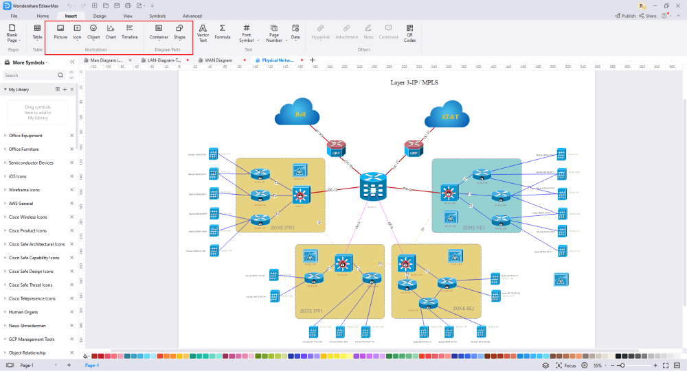
5. How to Draw a Physical Network Diagram in EdrawMax
EdrawMax is a simple, all-around diagram tool that allows you to create network diagrams and other types of diagrams without stress. It contains symbols such as mainframe, terminal, cloud, firewall, comm-link, printer, switch, server, router, bridge, and hub. In this section, we will describe the step-by-step process of drawing a physical network diagram in EdrawMax. Assuming you have installed EdrawMax on your computer, you can use the detailed network diagram templates instead of starting from scratch.
Step1 Open EdrawMax and Login
The very first step that you need to follow is to install EdrawMax in your system. Go to EdrawMax Download and download the network diagram software depending upon your operating system. If you need remote collaboration with your office team, head to EdrawMax Online and log in using your registered email address.
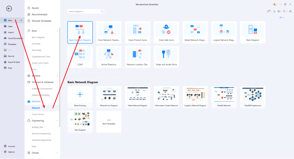
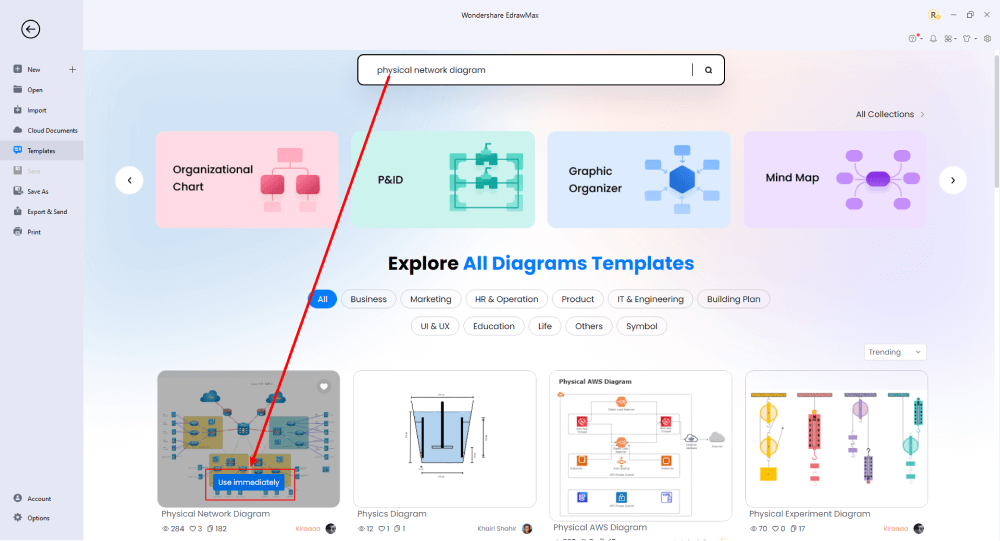
Step2 Select a Template
After launching, the Home screen opens by default. Head to the Template bar and search for Network Diagrams in the search box. In-built templates specific to your search will appear on the screen. EdrawMax features a large library of templates. We have more than 25 million registered users who have produced thorough Templates Community for each design. Select the template you like and click Use Immediately to open it in a new window for customization.
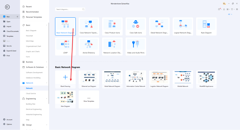
Step3 Create From Scratch
From the EdrawMax homepage, you will find the '+' sign that takes you right to the canvas board, from where you can start designing the network diagram from scratch. Coupled with your technical expertise, you can use a wide range of symbols to draw a detailed physical network diagram.
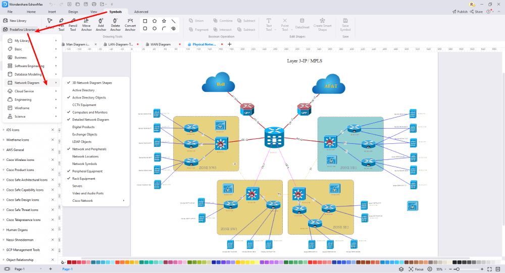
Step4 Select Symbols
EdrawMax includes a large number of symbol libraries. You may quickly build any type of diagram with over 26,000 vector-enabled symbols. If you can't locate the symbols you need, you can easily import some images/icons or build your own shape and save it as a symbol for later use. Simply go to the 'Symbols' part of EdrawMax and select the 'Predefined Symbol' section from the top toolbar. Hundreds of symbol categories are accessible for you to utilize and incorporate into your physical network diagram.
Step5 Add Components
After you have sketched out the basic pieces, you may customize the typefaces, colors, and other details by selecting the right or top menu to make your physical network design more visually appealing. Also, feel free to draw ideas from other layouts on Templates Community and transfer some of the photos or features that you think would go well with your physical network design.
Step6 Finalizing the Plan
Once your physical network diagram is ready, you can collaborate with your team to consider their opinion using the Cloud-base files. EdrawMax allows up to 100M free cloud storage. It supports files in several formats, including HTML, PDF, Graphics, Visio, Microsoft Office, etc. It is not a complicated process to create a physical network diagram in EdrawMax. You can take a template and continue customizing it to suit whatever design you want. EdrawMax has several templates with fantastic designs for a physical network diagram for your organization.

Basically, it is simple to create a physical network diagram in EdrawMax, just grab a template and keep customizing, drag and drop professinal network diagram symbols to make your plan better. If you are still confusing about how to make a physical network diagram in EdrawMax, you can find more tutorial videos from our Youtube.
6. Physical Network Diagram Examples
A physical network diagram represents the physical arrangement of several components that encompass the network, including hardware and cables. Normally, the diagram provides a bird's eye view of the network within the physical space. It is also possible to construct more professional network diagrams using free templates from EdrawMax. Just click the image to download EdrawMax, and download the network diagram templates accordingly. Then double click to open the templates and customize as your prefer. Or open the templates from EdrawMax Online , and duplicate the templates.
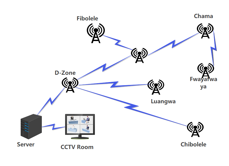
Example 1: Physical Topology Diagram
The image above shows a physical topology diagram for Kagem Mine CCTV. It describes how the devices are connected using wires and cables. The logical architecture of a shared Ethernet network employing hubs rather than switches, for example, appears to be as if each node is connected to a common bus that runs from node to node.
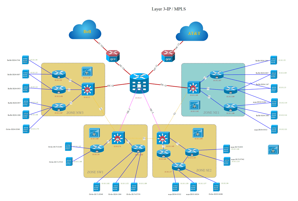
Example 2: Physical Network Layout
A physical network layout shows the link between devices through wires and cables. In EdrawMax, you have abundant Physical Network Layout templates to design whatever you want. Just like the human brain uses visual images to learn more, the same applies to physical network diagrams for professionals.
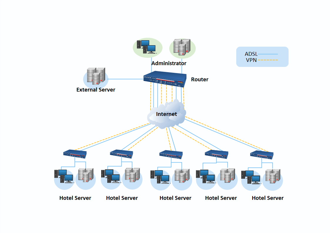
Example 3: Physical LAN
A network diagram illustrates the nodes and the relationships in a physical LAN network. This is shown in a schematic or diagram to demonstrate several network architectures. In EdrawMax, you can create several unique physical LAN diagrams using the pre-defined templates.
7. Free Physical Network Diagram Software
EdrawMax network diagram software is a comprehensive, robust, easy-to-use, and flexible software tool for creating charts and flow graphs. This unique tool allows professionals to create over 280 diagrams, including organization charts, room sizes, office layouts, fishbone diagrams, network diagrams, etc. The user-friendly interface allows you to quickly and unexpectedly implement your ideas, strictly catering to the needs of professionals in several sectors, such as business, strategic analysts, human resources, and management. Furthermore, due to its comprehensive compatibility, users can import and export their designs in various formats, including HTML, PNG, JPG, Microsoft Office, Visio, and PDF.
Below are EdrawMax's comprehensive features that will offer you an excellent drawing experience:
- EdrawMax contains various complicated layouts that allow users to create network diagrams quickly.
- It can be used for various things, including idea maps, flyers, banners, and business cards. In terms of general design, the capabilities are wide.
- It comes with numerous templates that can be used for various purposes. You can also create, save, and share your customized templates.
- EdrawMax works on Linux, Mac OS, and Windows.
- The user interface is easy to navigate, allowing even a novice to search for things.
- Since data import is automated, it is simple to visualize all data.
6. Final Thoughts
A physical network diagram is a diagram that shows how a computer or communications network works. It depicts the components that form a network and how they interact, such as routers, hubs, and firewalls. The article expounds on physical network diagrams, how to create these diagrams, and why businesses utilize physical network diagrams.
Although you might find several physical network diagram software online, none beats EdrawMax. The moment you start using EdrawMax , you will realize that the tool comes with several amazing features that ease your efforts in creating the physical network diagram and help you share the designs using the easy sharing option. With EdrawMax, you can export your file into multiple formats, and share your works on different social media platforms, like Facebook, Twitter, LinkedIn, and Pinterest. All in all, EdrawMax is a wonderful tool that caters to all of your designing and drawing needs.

Network Diagram Complete Guide
Check this complete guide to know everything about the network diagram, like network diagram types, network diagram symbols, and how to make a network diagram.
You May Also Like
Active Directory Complete Guide
Knowledge
Fire Escape Plan Complete Guide
Knowledge
Building Plan Complete Guide
Knowledge
Evacuation Plan Complete Guide
Knowledge
Blueprint Complete Guide
Knowledge
Floor Plan Complete Guide
Knowledge


