What is a Functional Block Diagram?
Know it All about FBDs
A Functional Block Diagram (abbreviated as FBD) is a graphical representation of a functional process via blocks and diagrams that is easier for a reader to understand and interpret. An FBD helps us determine the function between output variables and input variables via a set of rudimentary blocks and diagrams that are connected with arrows known as “connections.”
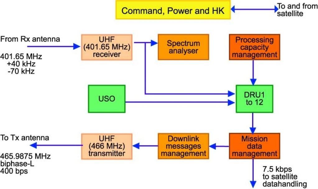
Source: www.esa.int
A Functional Block Diagram can help us create relationships between one or more than one variable (both input and output) to establish our understanding of functional processes aligned in a system.
These diagrams help us understand the functions and relationships between two or more variables widely used in software engineering, system engineering, and graphical programming language. For software engineers and programmers, FBD is an essential tool that helps them understand and create correlations between two or more variables by connecting them with a connection arrow.
Source: www.engineersgarage.com
A functional block diagram is also known as a functional flow diagram. As its name implies, it is a step-by-step representation of a functional flow that helps to simplify work processes and create a better understanding of them. The idea was given by Frank Gilbreth in 1921, preceded by other engineers and scientists who developed a multi-tier process model to simplify multiple functions and the relationships between them.
The latest functional block diagram continued to develop in the 1960s until NASA intervened and leveraged the concept to visualize and represent the time sequence of units in space systems.
Source: www.electronicproducts.com
And now, the Functional Block Diagram holds an advantageous position and is being widely used in various fields of Business Process Redesign, Business Process Management, Computer System Engineering, and System Engineering.
Though a functional block diagram simplifies the work processes, breaks down a huge process into smaller units, and helps us understand the relationship between two or more variables, it could still be trickier to understand and interpret the model. Thus, for your ease and convenience, we have mentioned the basics of an FBD.
All the functions are put in a functional block which is demonstrated by a box. A square box is a symbol of a function, as illustrated below.
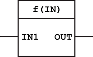
Source: www.plcacademy.com
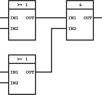
A functional block can have two or more two inputs and outputs. All these inputs and outputs can be connected with other inputs and outputs of the other functional block, thus establishing a relationship between the output of one function and the input of another as illustrated by the diagram below.
Functional blocks are standard but can be customized. Since you will be using the same functional block in your PLC program, you can use a functional block specific to one function and use it several times in other instances.
There are several types of function blocks. We have mentioned all kinds with a brief description of each block.
The basis of a function block is “logic” and is known to be the simplest form of algorithms. Within logic, there are two different gateway mechanisms or logic: AND logic and OR logic.
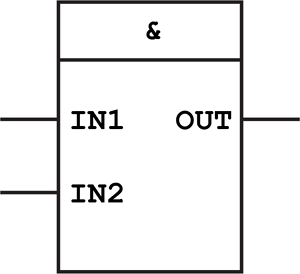
AND Logic Operation
If both the inputs are true the output will also become true.
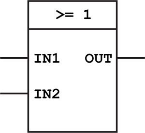
OR Logic Operation
If one of the inputs is true the output will also become true.
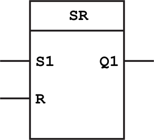
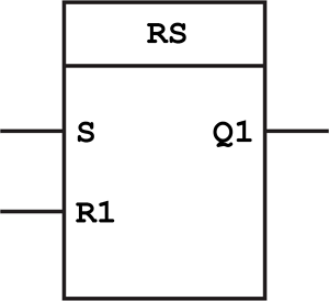
Bistable function blocks are known to be the simplest form of memory. It is up to you if you want to reset or set an output. The output will learn and remember the last point of the set input.
Set/Reset function block (set dominant)
Reset/Set function block (reset dominant)
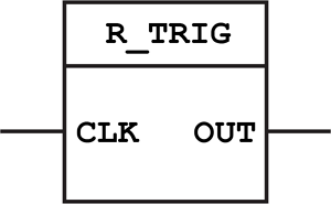
The next type of function block is Edge Detection. This type of function block is very useful and widely being used in PLC programming and electronics. It got its name because the input detects a progressive edge the output will be set. And it gets detected because the output develops a pulse when a positive edge is detected.
R_TRIG function block for detecting rising edge signals
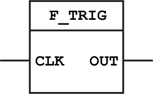
F_TRIG function block for detecting falling edge signals
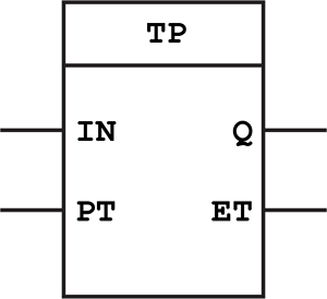
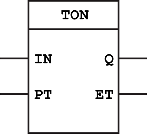
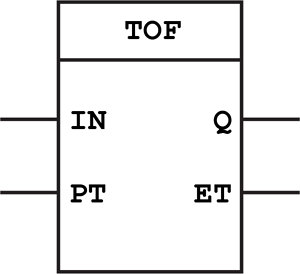
They are also being used in PLC engineering on a wide scale. There are three types of timer function blocks. These types of blocks include an on-delay timer, off-delay timer, and pulse timer. You will need to use only one timer and derive all the timers out of that timer.
Pulse Timer (TP) function block
On Delay Timer (TON) function block
Off Delay Timer (TOF) function block
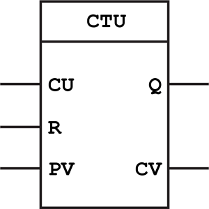
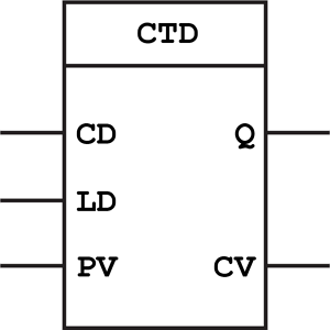
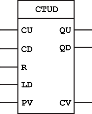
The fact about the counter function block is that it takes inputs and outputs and contains other types of data. There are three types of Counter Function Blocks. These types include Up Counter, Down Counter, and Up-Down Counter blocks.
Up Counter (CTU) function block
Down Counter (CTD) function block
Up Down Counters (CTUD) function block
If you want to use these templates, you can click to download them. While The eddx file need to be opened in EdrawMax. If you don’t have EdrawMax yet, you could download EdrawMax for free!
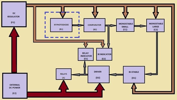
As shown in the diagram, a central processing unit performs functions, receives inputs from the user, and converts them into outputs to display to the user via output devices. This is the Functional Block Diagram of a typical process that occurs in a computer system. This was illustrated by computer system engineers differently using different kinds of function blocks.

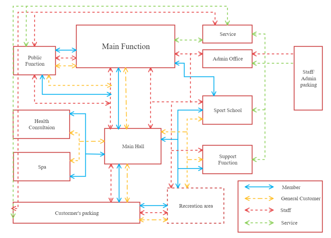
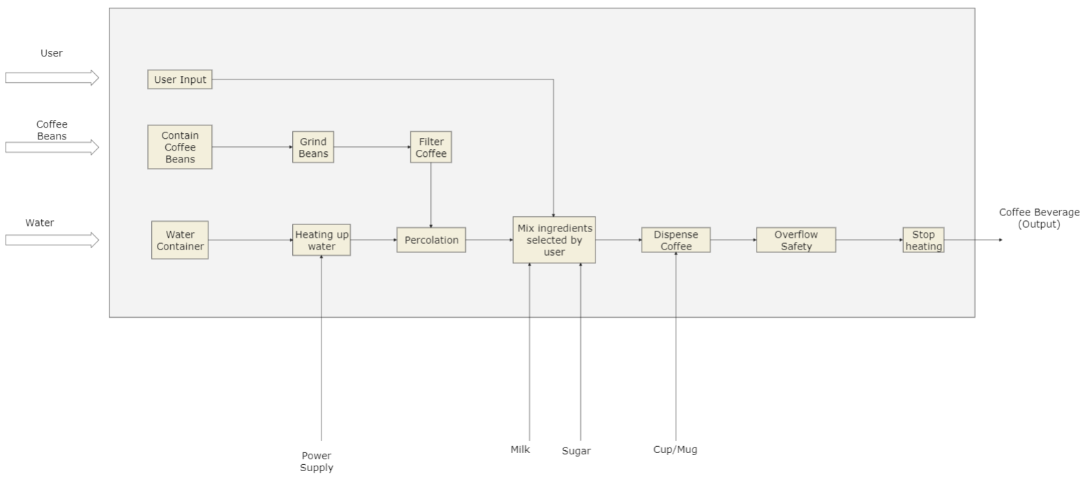
The Function Block Diagram (FBD) is a graphical language for designing programmable logic controllers that can describe function input and output variables. A main function in the block diagram is described as a set of elementary blocks, as shown in the image template below. At the same time, the blocks' inputs and outputs are connected via connection lines or links. The main functions are represented in the image by blocks connected by lines that show the relationships between the blocks.
Click to Download Main Function Block Diagram Template >>
While The eddx file need to be opened in EdrawMax.
Click to Download Functional Block Diagram Template >>
While The eddx file need to be opened in EdrawMax.
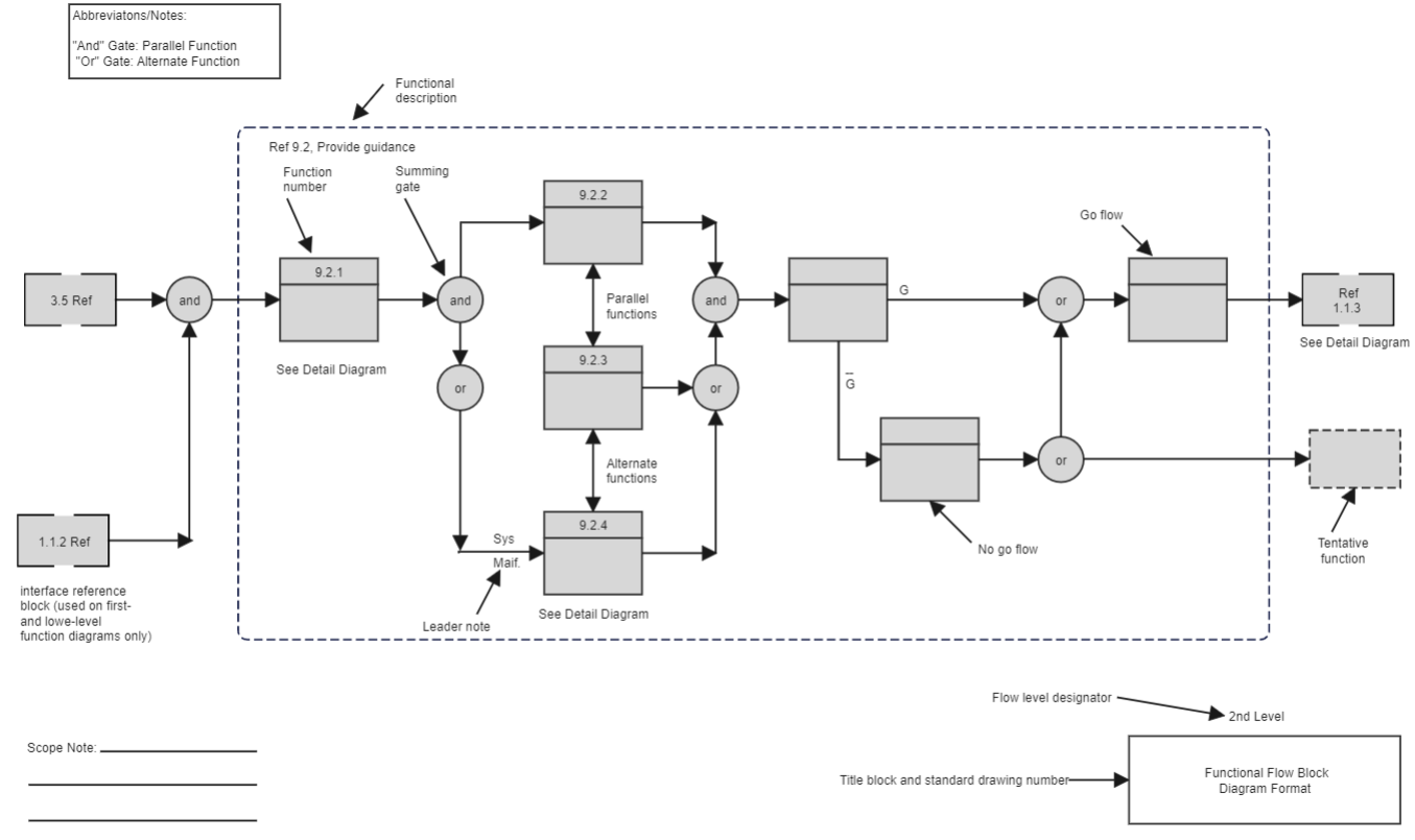
A functional flow block diagram is a multi-tiered, time-sequenced, step-by-step flow diagram of a system's functional flow (FFBD). In this sense, the term "functional" differs from its use in functional programming or mathematics, where the terms "functional" and "flow" would be confusing. The order in which activities are carried out is referred to as "functional flow," with "flow" arrows indicating the reliance on the success of previous processes.
Click to Download Functional Flow Block Diagram Template >>
While The eddx file need to be opened in EdrawMax.
Creating an FBD is not an easy task. However, we have mentioned the tips and techniques that you can use to create your FBD.
First of all, you can make a start by playing with automation like the TIA portal or Codesys. Then, it is highly recommended for people who want to create their FBDs by the programmers.
You can use functional block diagram programming to start creating simple yet easy PLC programs.
In addition to this, you can use several standard blocks for different functions to give an overall look to your FBD.
Since a functional block diagram is a very powerful tool that is widely being used in various fields of computer designing, system engineering, and business process reengineering, therefore, creating a functional block diagram to simplify the processes and to understand the relationship between two or more than two input and output variables could be a bit tricky.
Various intelligent tools are available on the internet that can help you create your functional block diagram. Amongst many tools and software, EdrawMax tops the list when it comes to drawing 2D diagrams. It can help you make your FBDs with different functional blocks with an easy, user-friendly interface. In addition, EdrawMax has various built-in tools that you can use to draw different types of FBDs.

・ Simple alternative to Visio
・ 26k+ symbols
・ 10K+ free templates
・ 10+ AI diagram generators


