Trailer Wiring Diagram: A Complete Tutorial
Know it All about Trailer Wiring Diagram
EdrawMax Wiring Diagram Software creates professional wiring diagram for free with easy-to-edit templates and symbols. Give it a try!
If you recently bought a trailer or finally decided to connect your already present one to your pickup. We have all your concerns covered in this article on the different types of wirings used and how to get your trailer connected with your car perfectly.
A trailer is an unpowered vehicle and is supposed to be towed by another vehicle: SUVs, pickup trucks, or jeeps commonly tow trailers. They can also be recreational vehicles depending on their type.
A trailer is a separate extension vehicle that needs to be linked with the primary vehicle. The trailer is attached to the primary vehicle by the appropriate hitch. To make the trailer’s electric output work, we use different connectors to ensure that depending on the outputs we require. The minimum output connector is the 4-Way connector, providing electrical output to the trailer's signals and ground and tail lights.
The trailer has several applications depending on the user and what kind of services one might be looking for. They are used for transporting goods, materials, boats, camping utilities, etc. The different types of trailers are as follows:
The most daunting task in regards to a trailer would be connecting it with your primary vehicle. If you are worried about how you can achieve this, color codes have got you covered. The trailer wiring has different colors that make it easy to understand and link up the wires with the primary vehicle and the connector.
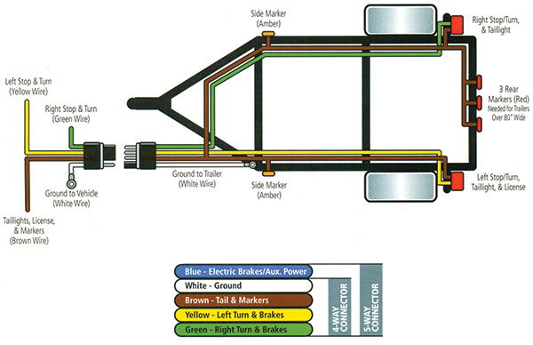
Trailer wiring has different color codes assigned for each wire to make it easier to connect the wires. To understand the color codes better, here is a comprehensive chart.

This chart shows what each color code stands for, which makes it very easy to coordinate which wire goes where.
As you can observe from this 4-pin trailer wiring diagram, the white wire is connected to the ground. The green runs at the back to connect with the right turn. The brown wire, which is responsible for handling the taillights, leads to both the light bulbs at the back, and the yellow wire runs back to the left to indicate a left turn. They are all connected by a 4-way connector.

4-Way connectors are the most basic connectors used for hooking up your trailer with the primary vehicle. The 4-Way connector allows you to control the three essential light functions: the break, right turn, and left turn. The fourth wire (White), as shown in the diagram, is the ground wire. Usually, light-duty trailers use this connector.
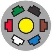
In this 5-pin trailer wiring diagram above, you can see that the first wire is the ground wire (white). The second wire (green) to originate from the connector is responsible for the right signal. The third (brown) wire is the one that is responsible for the taillights. These are also connected to the side to ensure increased visibility.
The fourth wire (blue) is the one that indicates when the brakes are applied. The last set of wires (yellow) leads to the left side to indicate the left signal. These are connected via the 5-Way connector.
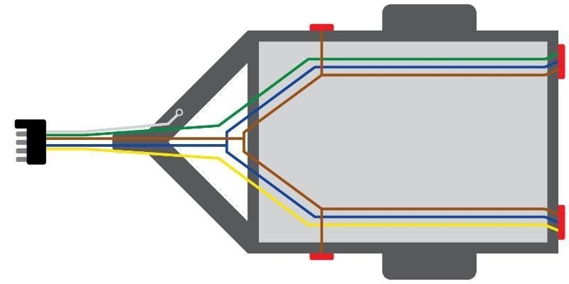
A 5-way connector is used to establish an electrical connection between the trailer and the primary vehicle. It is usually used by vehicles that use hydraulic or surge brakes. One pin is used for grounding; the other commonly used are for indicating turns, breaks, and that the car is running.
The extra wire is connected with the backup lights that help disengage the hydraulic coupler of the trailer when the vehicle starts to reverse; this turns off the brakes of the trailer. So this wire also serves as the reverse light.

In this 6-pin trailer wiring diagram, as it can be observed, there are two new wire positionings. The blue wire responsible for the hydraulic brakes is now used for electric brakes. The black wire is an indicator for the +12v battery attached to the trailer—the other wires are in the same fashion as the previous trailer diagrams.
The 6-way connector helps establish a connection between the primary vehicle and the trailer. It is used for brake control (mainly electric brakes) and are commonly used on campers, gooseneck trailers, and horse trailers.
This connector provides additional electrical support for a 12-volt battery via the black wire and electrical breaks via the blue wire.

The 7-pin trailer diagram has three different variations depending on the type of connector in which the wiring configuration is also different. These different 7-pin trailer wiring diagrams are as follows.
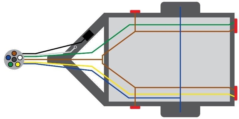
In this 7-pin trailer wiring diagram, the red wire provides auxiliary power to the trailer while the black wires are shifted to indicate the reverse lights. The other wire functionalities and placements are similar to those in a 6-pin trailer diagram where white is for ground, green is for right, yellow is for left, brown is for tail lights, and blue is for electric brakes.
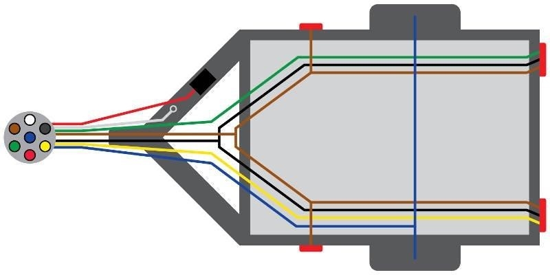
This 7-pin trailer wiring diagram shows that the colors of the wires have been changed for the reverse lights and battery source. The red color has been changed to orange and black to grey. The other colors remain the same for the other wires and their functionality as well.

In this 7-pin trailer wiring diagram, most of the wire configuration is changed. The brown wire connects with the right light. The green wire connects with the taillights, the yellow wire connects with the reverse lights, and the red wire connects with the left light.
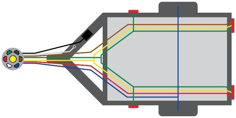
While the black wire connects with the battery, the blue wire connects with the electric brakes, and the white wire is connected with the ground. Connecting these in the correct order will ensure that the trailer lights work perfectly in sync with your primary vehicles.
 |
 |
 |
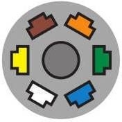
| 7-Way Connector | 7-Way Connector SAE | 7-Way Connector Traditional |
The connector helps you connect the wiring of your primary vehicle with that of your trailer. These are usually used for large campers, SUVs, trucks, commercial and agriculture trailers. Above are the three different connectors used for the wiring of a 7-pin trailer light system.
It is necessary to know the proper configuration of your trailer so that you can wire it ideally and your trailer lights work in sync.
We would recommend that you use EdrawMax Wiring Diagram Software for making trailer wiring diagrams. There are several templates that you can use to make the perfect trailer wiring diagram after seeing the configuration of your car.


