Inverter Circuit Diagram: A Complete Tutorial
Know it All about Inverter Circuit Diagram
EdrawMax is able to create free asset mapping and models for software development teams with ease. Give it a try!
The inverter is an electronic device used to convert Direct Current(DC) into Alternating current(AC). The Alternating Current is a current that consistently changes its magnitude with respect to time. This current flows only in one direction. The Direct Current is also a one-directional current that usually flows through a conductor, but sometimes it can also flow through the insulators.
These inverters are used to the work that is opposite to the converters. It does not produce power, but the DC source also produces it. Usually, the inverter is an electronic device, but sometimes it can be made with mechanical components. They are ordinarily used in applications where voltages and high-current are present. The efficiency of the power inverter is more than 95%. The power inverters are also used in controlling speed and torque in electronic motors.
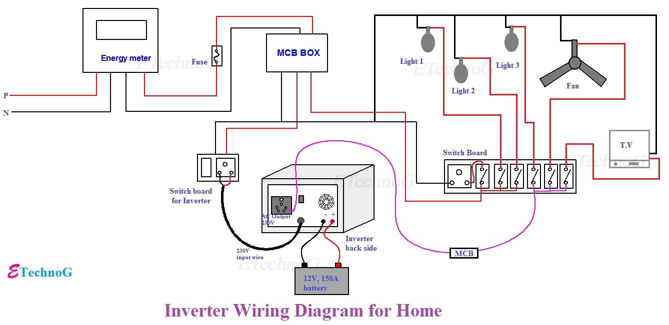
You may also want to make your own inverter wiring diagram:
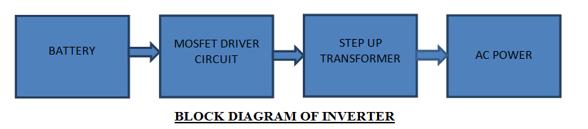
The inverter is made to give a voltage of 220V AC or 110V AC to the device connected with it at the output socket as a load. When the AC main supply is open, the inverter sensors consider it and pass this AC to the relay plus battery charging section. From the relay, the AC will pass to the load that is managed by the line voltage. This line voltage is also produced to the battery charging section, converting it to the direct current.
Following are the main types of inverters that you should know.
These are the basic types of inverters with no more advanced features. They are used in typical home appliances like air conditioners, refrigerators, washing machines, computers, televisions, etc.
These are the inverts that are cheaper than the inverter, as mentioned above. They are used in low electrical devices like fans, bulbs, microwave ovens, etc. They convert 12-volt batteries and recharge them with solar panel generators.
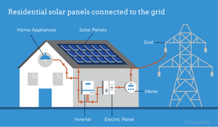
These are the inverters with more advanced features, and instead of using traditional energy, they use solar energy to convert Direct current to Alternating current.
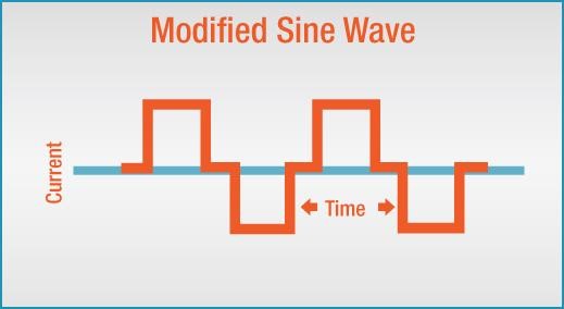
The inverter internally is made up of switches, a transformer, a battery, a MOSFET, and an amplifier. The DC which is stored in the battery is altered to the AC. The switches play an essential role in this process, where they are continuously turned ON and OFF. The MOSFET, a transformer, also consistently turns ON and OFF the DC voltage, making an opposite voltage, an alternating voltage.

・ Simple alternative to Visio
・ 26k+ symbols
・ 10K+ free templates
・ 10+ AI diagram generators
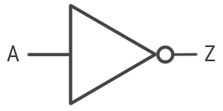
Before jumping into the inverter circuit diagram, it is necessary to know the logical symbol of the power inverter. In the electronics or logic design subject, the inverter is also known as the NOT gate, which does nothing but logical negation. Elaborating more, the inverter or NOT gate makes the high a low and the low a high.
The inverter is an important topic in the electronics and logic design world as the state machines, decoders, multiplexers, etc., use it for their working. In the same topic, if you have no inverter that is NOT gate, you can make it with the combination of NAND and NOR gate.
The logic symbol of the inverter is illustrated below.
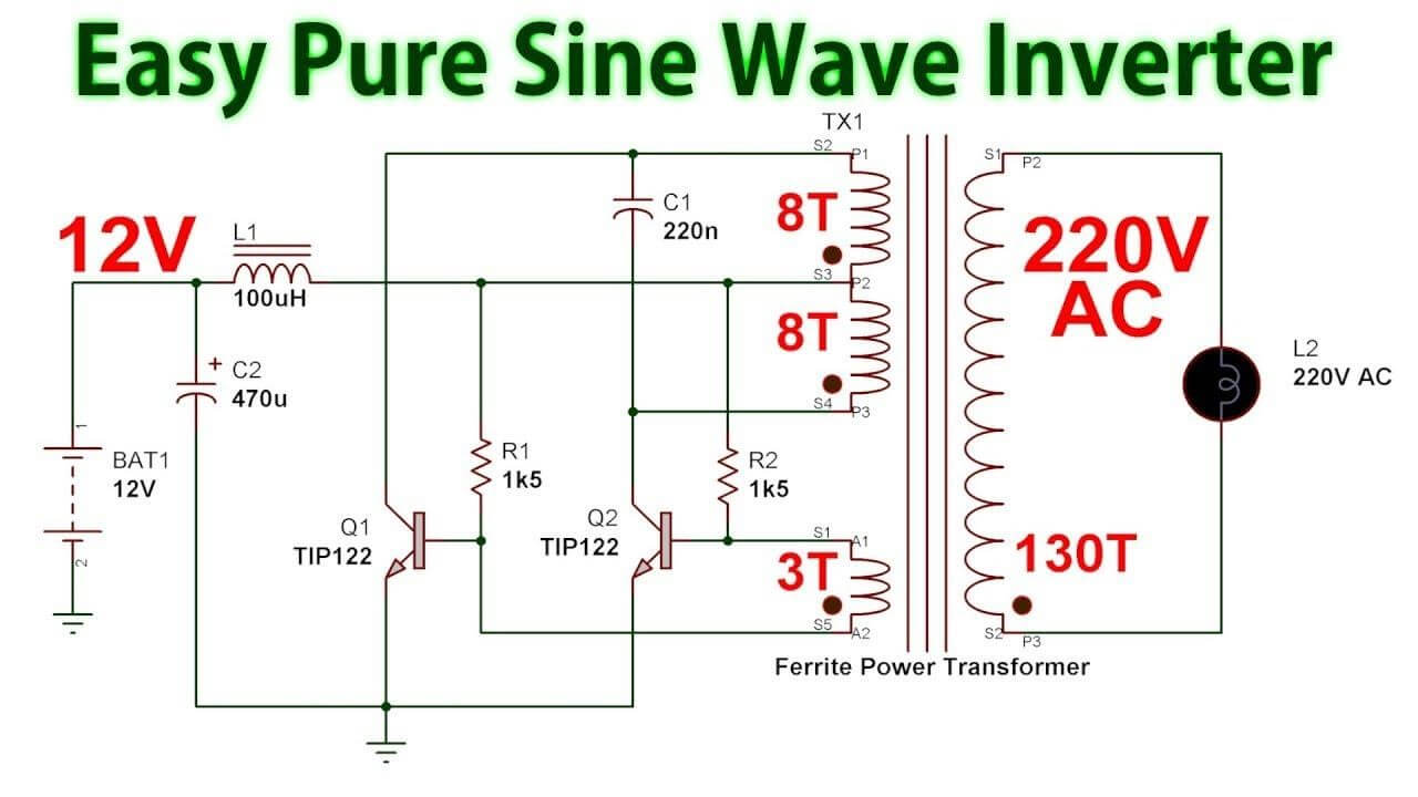
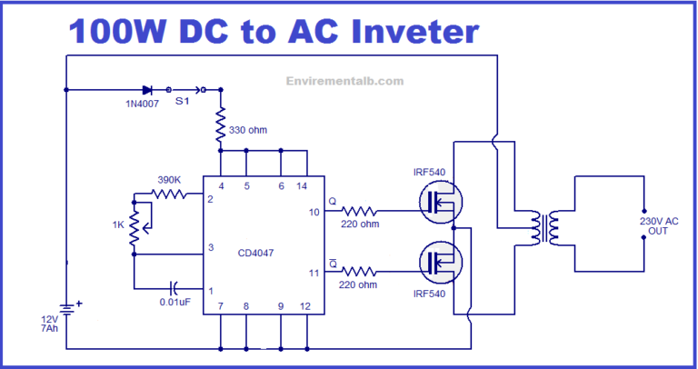
This section will tell you about how to make a simple 100-watt inverter circuit diagram. In the home or industries scenarios, you normally purchase it from the market, but when you have to make it with your hands for project purposes, you can follow these steps accurately.
You will need the following things to make an inverter.
The best way to design an inverter circuit diagram is to use computer software readily available on the internet. Software like EdrawMax has all features to make a perfect circuit diagram. You can also use any diagram-making software.
The inverter plays a vital role in our daily life. The equipment that uses inverter saves energy costs up to 50%. These types of equipment make less noise than the equipment without inverters. Plus, they are more stable while working.
The inverters can easily manage the changing temperatures of the devices. They can easily calculate the voltage, current and then work according to it.
What are you still hesitating about?
Follow the video and try to make your own inverter wiring diagram:


You can use EdrawMax for making a circuit diagram of an inverter. The EdrawMax is a reliable, easy-to-use software that makes your diagram more perfect. This software is used for diagram making. It contains all the necessary features and libraries that will suffice you in your diagram making.
The software is free to use for primary diagram making, but you have to go for the pricing option to use more advanced features. The software allows you to import your templates or use their pre-generated templates. Plus, this software allows you to download your project in multiple formats too.