Relationships in UML Class Diagrams
Know it All about UML Class Diagramand their Relationships
EdrawMax UML Class Diagram Tool is able to create free UML diagrams and models for software development teams with ease. Give it a try!
Class diagrams are one of the most important and useful UML diagrams that illustrate the structure of classes and their relationship with each other. However, people often face trouble creating them because of their inability to understand the connections and links between classes. The article below covers everything in detail and thoroughly discusses the different class diagram relationships.
Read on to learn everything about class diagrams and how to create them in a wink of an eye with EdrawMax.
In object-oriented programming, classes are a user-defined blueprint for an object. It maps out the characteristics, methods, or qualities common to all objects of a certain kind. Likewise, objects are also a fundamental part of object-oriented programming that is created based on the set of rules of a class. Objects and classes work simultaneously, and none can be discussed without the reference of the other.
Based on this concept, class diagrams are drawn in UML (Unified Modelling Language) that illustrate the attributes, relationships, and operations between objects. Class diagrams are the foundation of software and are static structure diagrams that work according to the principle of object orientation. They help in data modeling, conceptual modeling, and translating the models into programming codes.
The primary purpose of a class diagram is to design and analyze the static view of an application. A UML structure diagram defines the set of instructions of a system and works to design the representation of reality. These diagrams are especially very useful when generating source codes. They are an excellent way of demonstrating the inter-relationships between objects owing to their attributes and operations.
If you wonder how to create UML Class Diagram in a minute? Try EdrawMax UML Diagram Tool to use pre-made templates and edit by yourself!
The class diagrams are illustrated by drawing diagrams that are further divided into three partitions.
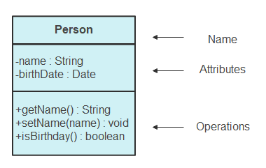
All the classes exhibit a variable access modifier level depending on their visibility. The visibility markers limit people who can access the information in a particular class. Here are visibility markers and their access information:
| Marker | Visibility | Description |
|---|---|---|
| + | Public | All classes can view the information. |
| - | Private | Information is hidden from all classes outside the partition. |
| # | Protected | Child class can access the parent class inherited information. |
To specify the direction concerning the caller, the operations can be labeled as 'in,' 'out,' or 'inout.' The parameter directionality is specified before the parameter's name.
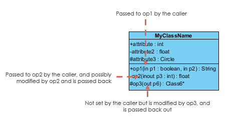
Source: www.visual-paradigm.com
Here to get a useful UML Class Diagram Tool for creating UML diagram with ease!
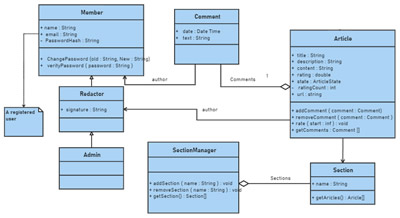
In a class diagram, all classes are linked with each other by proper relationships. These links aid the user in understanding the connection between different entities thoroughly. However, due to the slight similarities, many often have trouble understanding the different class diagram relationships.
Read on to learn the different types of class diagram relationships, their notation, and what they indicate in a UML diagram.
Associations are used to represent the family links and signify the static relationship between classes. It structurally connects two or more classifiers and lists their attributes, properties, and associations. The associations are represented by a solid line drawn between the two classifiers.
Associations are further divided into four types: uni-directional, bi-directional, aggregation, and composition association.
Also called the directed association, this type of association refers to when an object contains another object in its field. This relationship signifies the flow of information between two classifiers. The association is represented by a solid line and an arrow pointing towards the container classifier.
This association is used when two classifiers are linked closely and can store each other in their fields. A solid line represents the association. The bi-directional association is the most common type of association used in UML diagrams.
Aggregation is a more specific type of association and shows the 'part-of' relationship in diagrams. However, this type can only link two classifiers and must have a binary association. In UML diagrams, it is represented by a solid line and a hollow diamond near the containing class.
This type of relationship is used to represent the dependence of objects on the focal entity. The focal classifier contains objects, but the contained objects are also deleted if the focal class is deleted. The composition relationships are represented by a solid line and a filled diamond shape drawn near the containing class.
EdrawMax UML Diagram Tool provide professional UML diagram templates for beginners and highly-customized drawings experience for experts! Give it a try!
In UML modeling, generalization is used to represent the parent class and child class relationships. A 'kind-of' relationship can be seen between the classifiers and how one entity is based on the other, inheriting the parent's attributes, operations, and relationships.
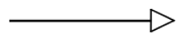
The parent model can have many child classes and likewise, a child class can have multiple parent models. In a UML diagram, generalizations are shown by a solid line, having an unfilled arrow pointing from the child class to the parent class.
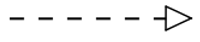
It is a relationship that links two model elements with one classifier realizing/implementing the behavior of another classifier. The realization relationship aids in understanding how interface affects the implementing class. The realization is represented by a dashed line with a hollow arrow.
You May Also Wonder: UML Class Diagram Examples
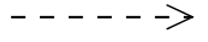
This is a weaker relationship type used when an object is not contained in any field. The dependency relationship will exist that change to one class will cause change to the other entity. It is represented by a dashed line and an arrowhead pointing towards the dependent entity.
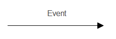
In UML modeling, the transition state is used to connect two composites/states directly. The states are credited as the major transition and main source of a transition. A solid line with a filled arrow is used to represent the change of control between two classes. Above the arrow, the event is labeled that causes this transition.
The activity diagram is an essential type of UML diagram used to represent the flow between different activities of a system. They aid in understanding the logic behind the algorithm of a system. The activity flow is represented by a solid line with a filled arrowhead pointing towards the next activity in the sequence.
Source: www.ibm.com
For UML modeling, class diagrams are an advantageous way of illustrating and visualizing the relationship between different classes and objects. The different types of class diagram relationships allow viewers to understand the connections more quickly and illustrate the application of an entire system. It is essential to use the correct arrows because a slight error can change the relationship type between the classes.
Learn how to create UML modeling diagram with ease! Try EdrawMax UML Diagram Tool to use pre-made templates and edit by yourself!
Drawing a UML class diagram can be overwhelming for someone new to this concept. However, if you have software like EdrawMax at your service, things will be faster and easier.
Edraw is a free, intuitive, and user-friendly tool that allows users to illustrate graphical notations and diagrams. With its gamut of tools and an extensive, highly customizable library of symbols, the software supports all types of UML diagrams. The software has a variety of templates for different illustrations that can be chosen to create diagrams in just a few clicks. Check out the amazing software for more options.