Series vs. Parallel Circuits: The Complete Breakdown
Learn More about Series & Parallel Circuits
Electrical circuits can be arranged in either series or parallel. Series circuits allow for electrons to flow to one or more resistors, which are elements in a circuit that use power from a cell. All of the elements are connected by the same branch. On the other hand, each of the elements in a parallel circuit have their own separate branches.
Here is a breakdown of the common terms and illustrations that you might come across when dealing with series and parallel circuits.
| Series: Definition + Illustration | Parallel: Definition + Illustration | |
|---|---|---|
| Current |
The amount of electricity flowing through a circuit, measured in amps using an ammeter. In this diagram, the current is represented by i. 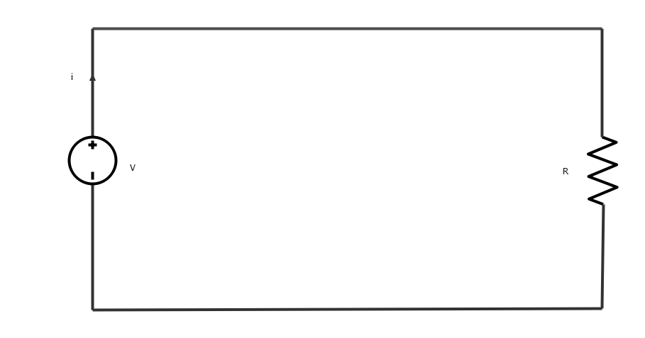
|
The amount of electricity flowing through a circuit, measured in amps using an ammeter. In this diagram, the current is represented by i. 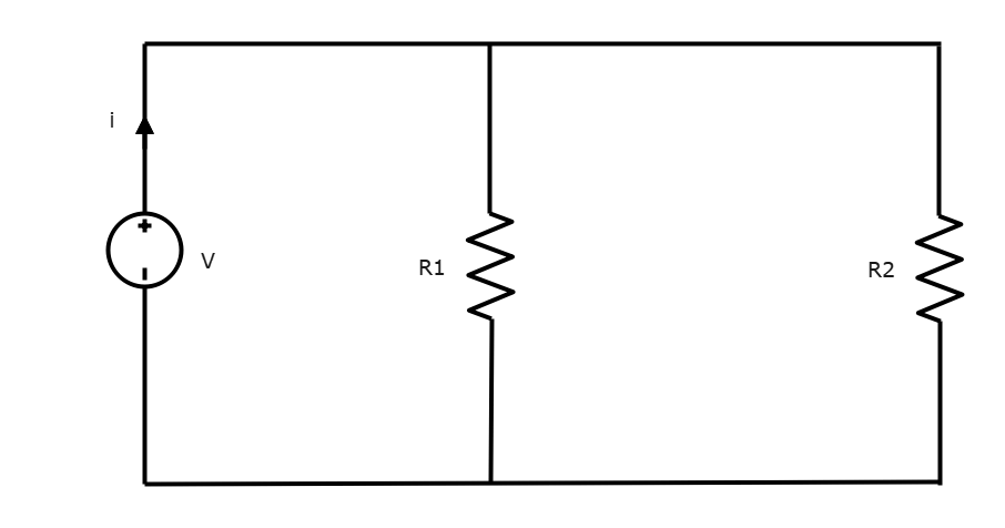
|
| Voltage |
Voltage can be thought of as a force that makes electric charges move in a wire or other kind of conductor. It is measured in volts (v) using a voltmeter.
|
Voltage can be thought of as a force that makes electric charges move in a wire or other kind of conductor. It is measured in volts (v) using a voltmeter.
|
| Resistance units |
Resistance is a measure of the amount of opposition against an electrical circuit’s current flow. Resistance is measured in ohms (Ω). 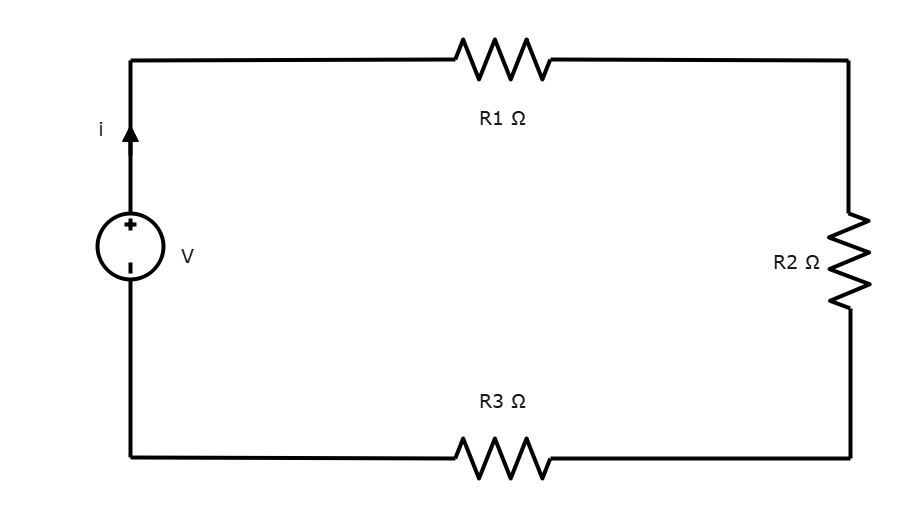
|
Resistance is a measure of the amount of opposition against an electrical circuit’s current flow. Resistance is measured in ohms (Ω). 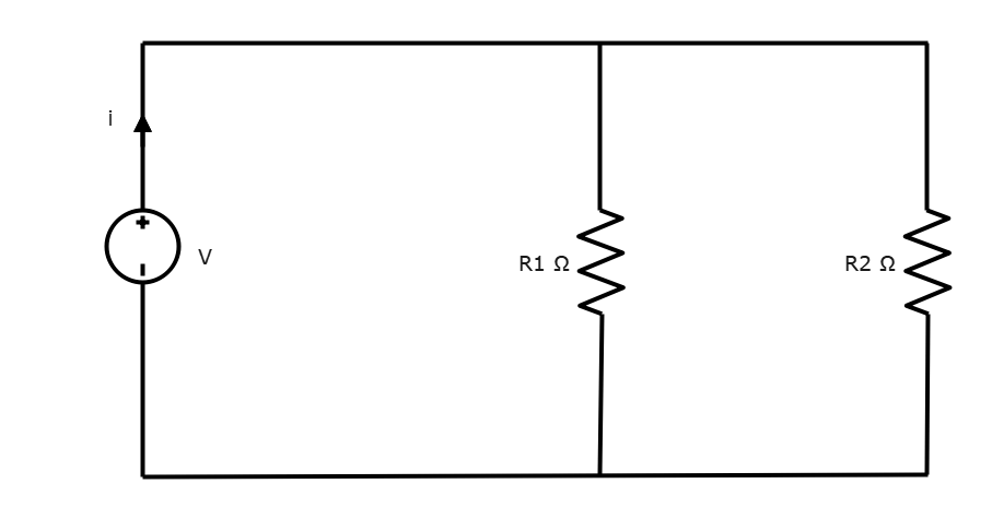
|
| Inductors |
When an electric current flows through an inductor, energy is stored in a magnetic field. It opposes any changes in current that goes through them. 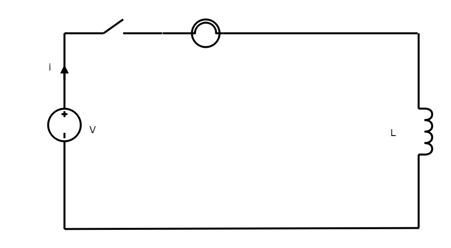
|
When an electric current flows through an inductor, energy is stored in a magnetic field. It opposes any changes in current that goes through them. 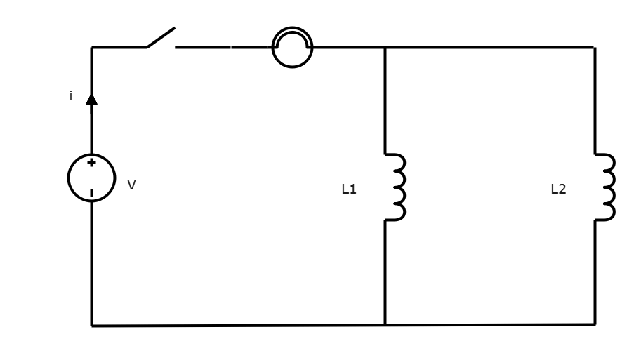
|
| Capacitors |
A capacitor is a passive electronic component that stores electrical energy in an electric field. 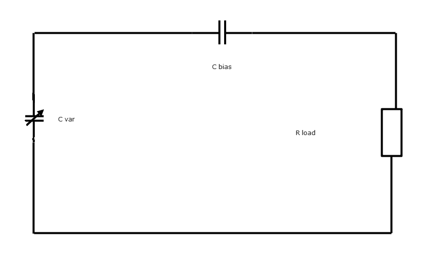
|
A capacitor is a passive electronic component that stores electrical energy in an electric field. 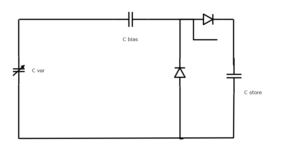
|
| Switches |
A switch is used to control the flow of an electric current in a circuit by inhibiting or initiating its flow. 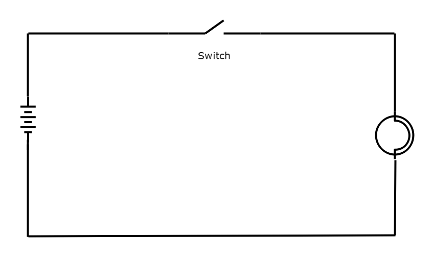
|
A switch is used to control the flow of an electric current in a circuit by inhibiting or initiating its flow. 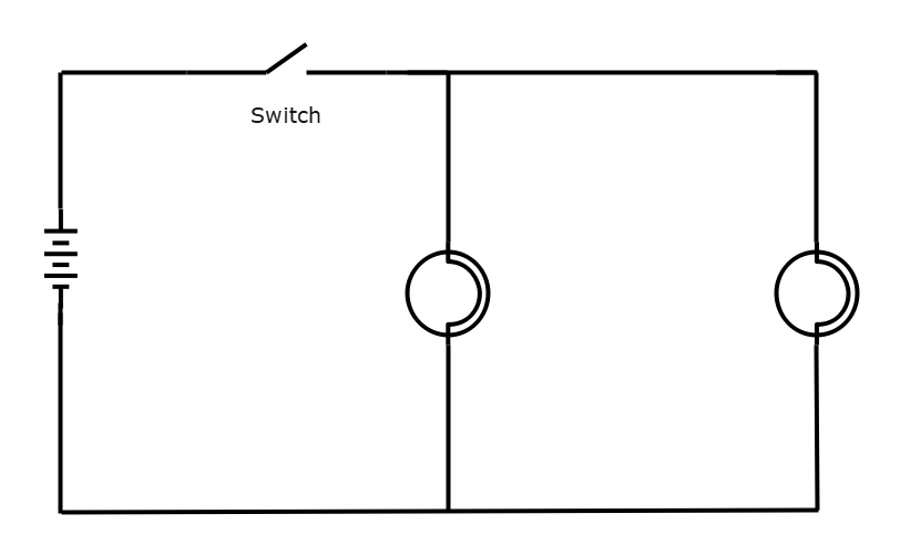
|
| Cells and batteries |
A cell or battery is an energy source that provides the voltage that gets the current flowing in a circuit. It has a positive terminal (+) and a negative terminal (-). The positive terminal is depicted by the longer horizontal line, and the negative terminal is depicted by the shorter horizontal line. 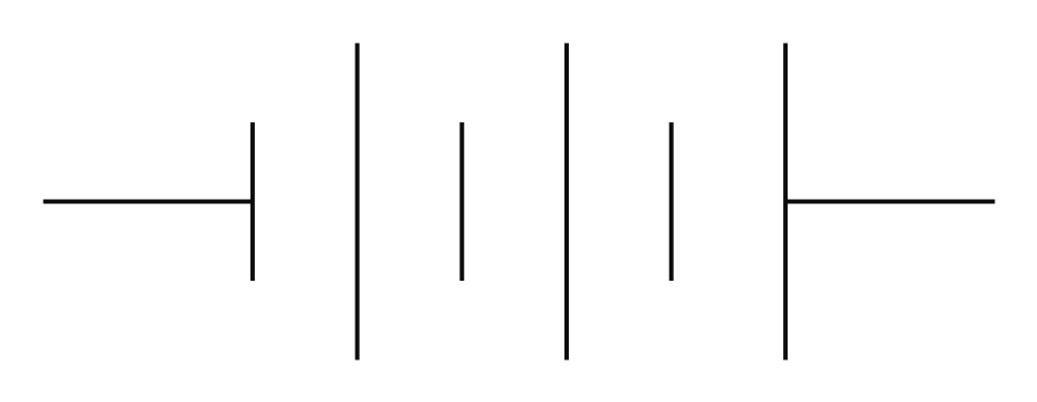
|
A cell or battery is an energy source that provides the voltage that gets the current flowing in a circuit. It has a positive terminal (+) and a negative terminal (-). The positive terminal is depicted by the longer horizontal line, and the negative terminal is depicted by the shorter horizontal line.
|
So now that we’ve covered some of the basics, let’s dive deeper into each of the circuit types.

・ Simple alternative to Visio
・ 26k+ symbols
・ 10K+ free templates
・ 10+ AI diagram generators
In a series circuit, the resistors are arranged in a chain along one branch. The current going through each resistor is the same. Each component in a series circuit is dependent on each other; if one component was removed, none of the components would turn on.
Series circuits are made up of series connections. All of the components are connected via a single path. The current can only flow through this one path. In this example, there is one path that the current can go through, passing from the cell to the switch and the two bulbs.
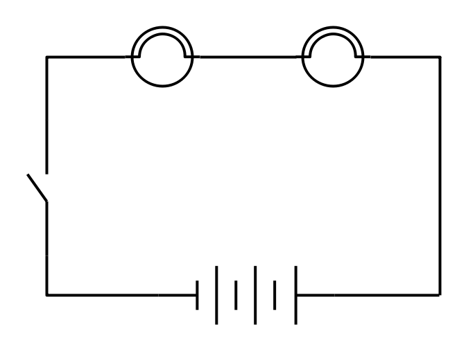
An example of a series circuit being used in a real life object is in a lamp. The circuit consists of a power source, a switch, the lamp, and back to the power source. Other examples of series circuits in real life objects include Christmas lights, refrigerators, freezers
In a parallel circuit, the current has to pass through at least two different branches. The current will divide among the number of branches. Each resistor will have a constant amount of voltage, but the current passing through each branch may vary.
Parallel circuits consist of parallel connections. In this type of connection, each of the components is connected across each other’s leads, as seen in the diagram below.
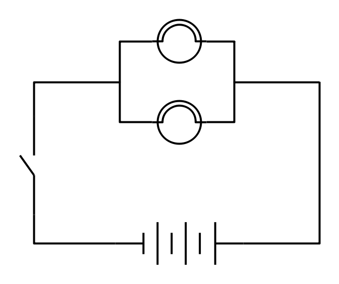
One real-life example of a parallel circuit can be found in the lighting and wiring setup in homes. All of the lights are powered by a single power source. If, for example, one light bulb burns out, the power source is still able to send voltage through to the other light bulbs, ensuring that the other appliances can continue to function as normal.
Here are two more examples of series and parallel circuits.
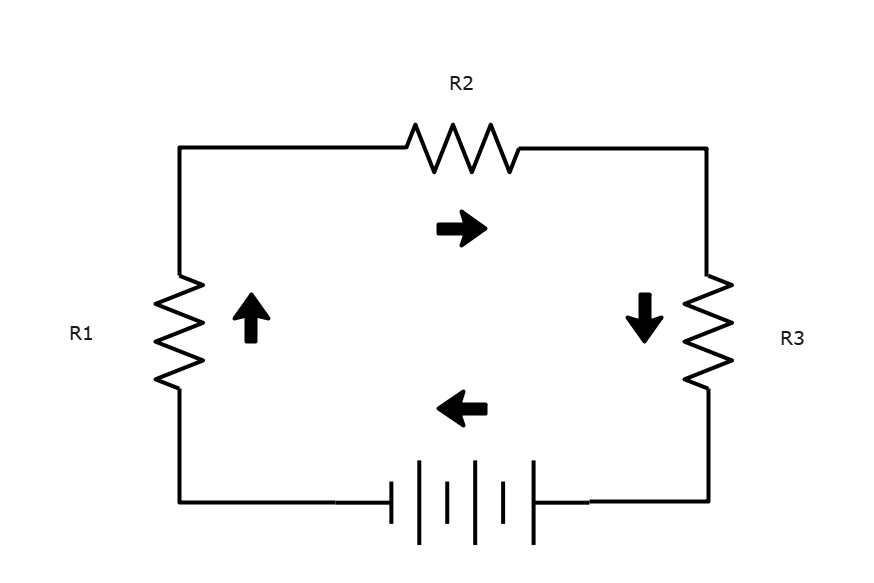
Series Circuit Example
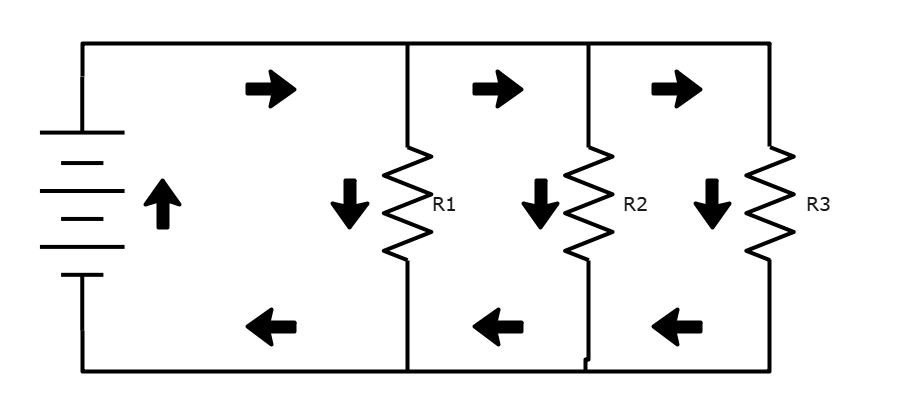
Parallel Circuit Example
When it comes to series vs. parallel circuits, each has different electrical properties that you must bear in mind when choosing which one suits your needs best.
So why choose EdrawMax? As you can see from the diagrams above, EdrawMax comes equipped with a plethora of symbols and diagrams, including all of the templates that you see above. Give it a try, and find out just how easy creating series and parallel circuit can be! Also, it contains substantial built-in templates that you can use for free, or share your series and parallel circuit templates with others in our template community.