UML Package Diagram
Part 1: What is a Package Diagram?
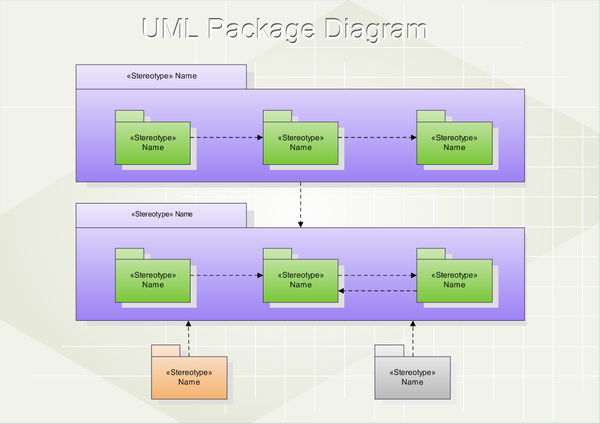
Package diagrams can be defined as structural UML diagrams that show the organization and arrangement of various UML elements in packages. A package that is the building block of a package diagram, is a grouping of related model elements. These model elements can be diagrams, documents, classes, or even other packages. A package is represented by a file folder symbol in the diagram with nested elements that can have a hierarchical arrangement.
Package diagrams reflect the organization of packages in the system and their elements. In the implementation phase, packages are translated as namespaces.
Part 2: Purpose and Benefit
Package diagrams have many applications in various types of systems and projects. The most common purpose of using package diagrams is an organization of use case diagrams and class diagrams. They are also used to provide a visual organization of the layered architecture within any large-scale software system. Package diagrams also clarify the import and access dependencies between different elements like packages, classes, and components.
The versatility of package diagrams allows us to illustrate both structure and dependencies between subsystems or modules through these diagrams. These diagrams also contain packages that have use cases showing the functionality of a software system. The dependencies between these packages are represented by labels or stereotypes, indicating the communication mechanism between the layers.
Package diagrams are used in large-scale systems to picture dependencies between significant elements in the design and depict a compile-time grouping mechanism.
Package diagrams are handy in software development, especially in object-oriented projects. They allow encapsulation and the grouping of different artifacts to make the system easy to understand, execute and maintain. Other benefits of the package diagram are:
- Package diagrams simplify the class diagrams by grouping similar elements. This grouping can be done on various grounds, including the domain, type, or functionality of the classes or the other artifacts. As a result, packages make the class diagram look clean and precise while making the implementation more modular.
- Package diagrams show a clear view of the hierarchical structure of the different elements in a system.
- Package diagrams are a great aid when you need to show only the high-level view of how a large-scale project is organized.
- Package diagrams support the evolution of a project from a simple design to a detailed structure. They can start with a broader understanding of the components needed and eventually evolve to a concrete system.
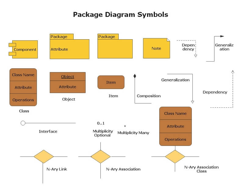
Part 3: Package Diagram Notations
Here are the essential components you'll find within a package diagram:
- Package
- Packageable element
- Dependencies
- Access dependencies
- Import dependencies
The package is a namespace that groups logically related elements together within a system. This is the building block of any package diagram. Each element that is included in the package must be packageable and have a unique name.
What is a packageable element? It is a named element that is owned directly by a package. Packageable elements are events, components, use cases, and other packages as well.
Dependencies are visual representations of dependability or influence of one element to the other element or set of components. Dependencies are divided into two groups.
Access dependencies show that one package requires assistance from the functions of another package.
Import dependencies show that functionality has been imported from one package to another.
Another way of classification of dependencies can be done on other bases as well.
- Usage Dependency
- Abstraction
- Deployment
- Subsystem
- An external representation of the resources allocated by the subsystem.
- Internal view shows the subsystem implementation.
- Then, there is a mapping between these two factors.
This kind of dependency exists when a given named element requires another element for its full definition and deployment.
Abstraction relates to two elements that represent the same concept at different levels of abstraction within the system.
Deployment is another dependency that represents the deployment of an artifact to a deployment target.
Subsystems are used for system decomposition, which various parts of the system can represent according to specification and implementation.
Part 4: How to create a Package Diagram in EdrawMax
EdrawMax is a leading drawing software. It has a wide range of templates and symbol libraries that support quick and accurate package diagrams. Here are the steps to create a package diagram in EdrawMax.
Step 1: Launch the EdrawMax Software
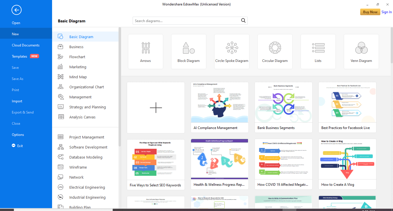
Step 2: On the navigation pane on the left side of the screen, click Software development>UML Modeling and wait for the templates to load. Then, choose a free template or click the + tile to create the diagram from scratch.
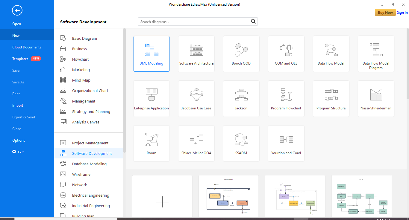
Step 3: When you click on a template, a pre-drafted diagram will appear on the canvas, and you can use it according to your requirements.
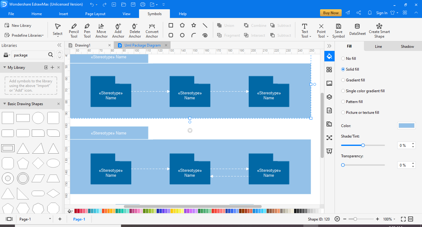
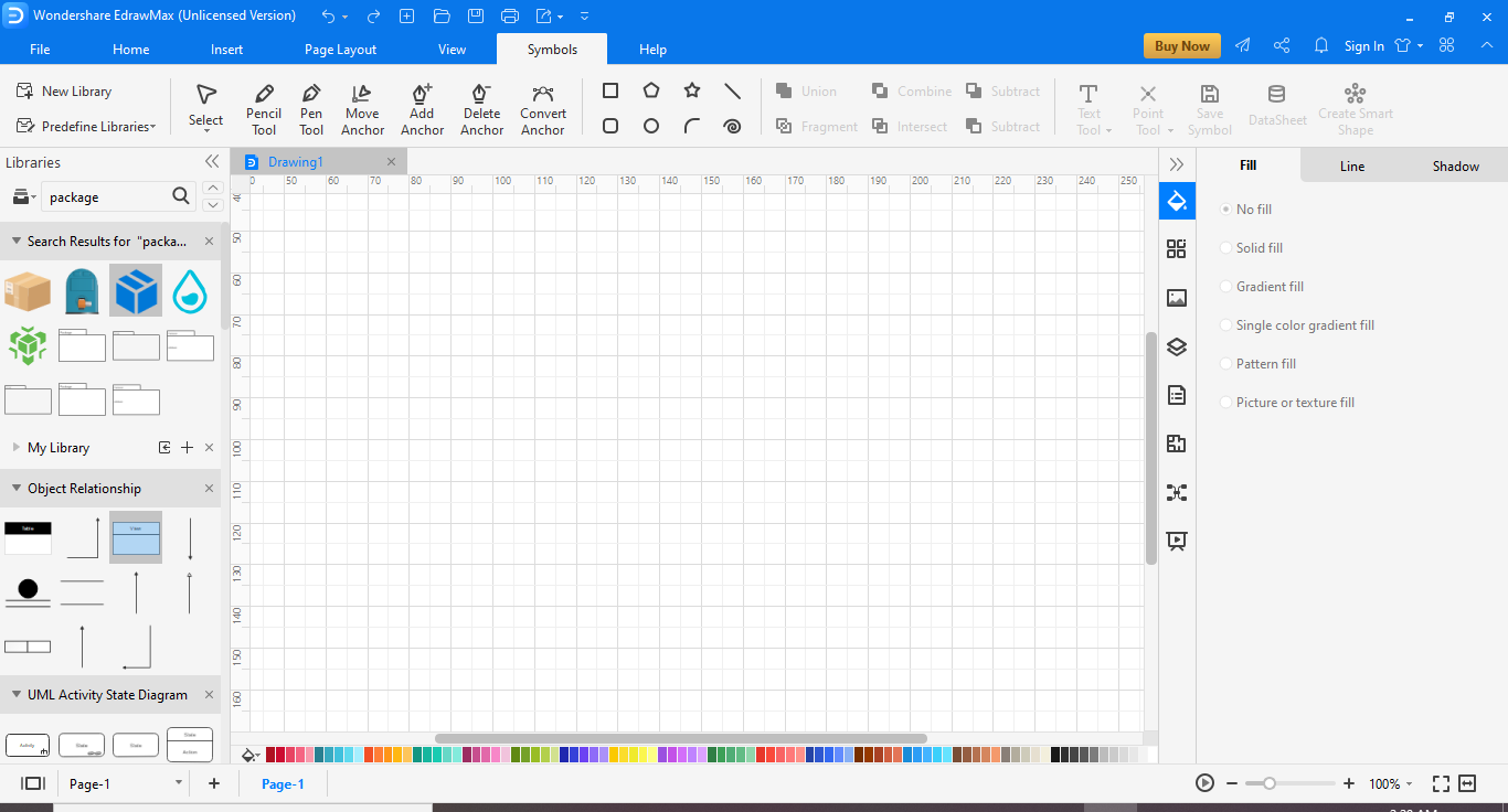
Step 4: To create the diagram from scratch, you can use the symbol library for symbols, drawing, and other visual tools. First, click on the icon next to Symbol Library on the left side of the screen to search for more symbols and icons. Then, scroll down to UML Modelling and select the required library.
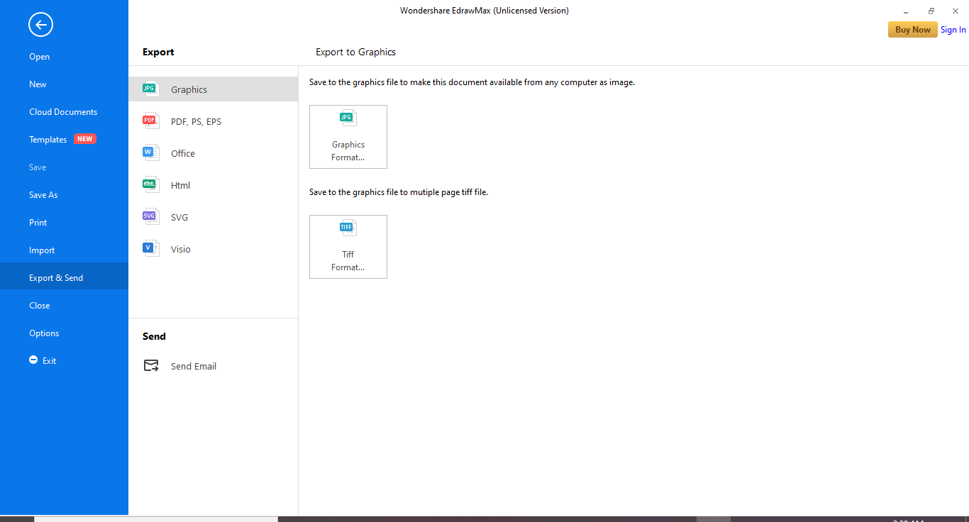
Step 5: Once you are satisfied with the results, save your File, and you also have options to export it to other formats like Excel, Word, or PDF. Click on File and then go to Export.

An all-in-one platform for 210+ diagrams.
・ Simple alternative to Visio
・ 26k+ symbols
・ 10K+ free templates
・ 10+ AI diagram generators


Part 5: Tips for creating Package Diagram
Package diagrams can be created at different levels of the project. Creating package diagrams differs based on the requirement and the level of details included in the package diagram. However, the general guidelines are the same for every situation.
- In an extensive system, you will define a subsystem for each separate part of a comprehensive system. Therefore, it is essential to make the creation of the package diagram easy and modular. So the design team can concentrate on a single part at a time.
- Though the package diagrams are high-level diagrams, and the team can postpone any decisions until the later part of the analysis and design. However, it would help if you still chose specification techniques depending on factors like system and subsystem.
- Now, analyze each subsystem in its own space. You will be using the specification as a requirements specification.
Part 6: Who Can Use Them and How
- Software developers: Represent software applications using the Unified Modeling Language (UML) notation.
- Software developers: Illustrate and interpret software application relationships, actions, and connections.
- Program managers: Show high-level static software structures in presentations and specification documentation.
Part 7: Examples of Package Diagram
Example 1
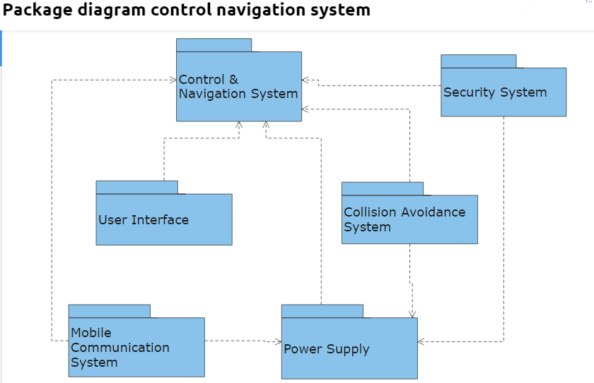
This is an example of a package diagram that is representing a control navigation system. In this diagram, the interdependency of different packages on each other is shown. The package names show that this is a very high-level package diagram. It simply represents a user interface package, but the details of the contents included in the interface are not shown.
Example 2