UML Interaction Diagram
Know it All about UML Interaction Diagram
UML Interaction Diagrams are the behavioral diagrams that provide a high level of abstraction of the system. It is a modified form of the Activity Diagram where the focus is on Interaction between objects and on overview of the flow of control of the interactions, which can also show the flow of activity between diagrams. The nodes in the interaction diagrams are the interactions or interaction occurrences.
An interaction is a set of interchanged messages between the object or actors to achieve specific specified tasks in the system. In the interaction diagram, the critical component is the Interaction, including messages and the lifeline.
The interaction diagram initiates the Interaction between the objects through the exchange of messages. In an interaction diagram, you will represent the relationship among different objects available within the system and the messages exchanged by them to communicate with each other.
Interaction diagrams help you to have a high-level view of the interactive behavior of a system. Interaction diagrams also show the way different objects in the system connect and interact with each other.
Interaction diagrams represent the dynamic behavior of a system. It shows how the communication between different lifelines in the system occurs.
In UML, the interaction diagrams are used for the following purposes:
There are two types of messages in a system. The messages are used to exchange information among objects or to request some information. Interaction diagrams are divided into several types depending on the kind of messages that they represent. The different types of interaction diagrams are sequence diagrams, collaboration diagrams, and timing diagrams.
The sequence diagram is a time-ordered sequence of events. It depicts the communication between two lifelines and the order of the flow of messages within the system.
The collaboration diagram is also known as a communication diagram. Its purpose is to focus on the structural aspects of a system and how various lifelines in the system connect.
Timing diagrams focus on the instance at which a message is sent from one object to another object. Thus, timing diagrams show interactions with a focus on the reason for time.
Here are some standard terms and symbols that are used in the interaction diagrams.
A lifeline shows a single object in a given interaction. It describes how an object participates in an interaction.
Here are the attributes of a lifeline:
● Name: is optional and shows the lifeline in a specific interaction.
● Type: Names the classifier.
● Selector: it is used as a Boolean condition like a decision node to select a particular instance that satisfies the requirement.
A message is a type of communication between two lifelines in an interaction. You may use it to exchange information and invoke an event like a call for operation, create or destroy an object, or send a signal.
The messages used within an interaction diagram can be classified as follows:
An operator describes how the messages will execute the operands within an operation. And it also supports operations on data in the form of branching and iterations.
Different forms of operators in an interaction diagram are following:
It is like a decision artifact. In branching, guard conditions go with the individual messages. These guard conditions verify if a message can be sent forward or not. If the message's guard conditions are true, can they be sent forward? A message can have numerous guard conditions, and numerous messages can work on the same conditions.
Interaction consists of an interaction specifier and an iteration clause. Parallel iteration specifiers are used to show parallel messages. This is represented by *//. In UML, iteration works by using a loop operator.
A state represents a situation or condition during the lifetime of an object. It is used to satisfy a constraint, perform various operations, or wait for an event. For example, a message can trigger a state change.
Step 1: Launch the EdrawMax program.
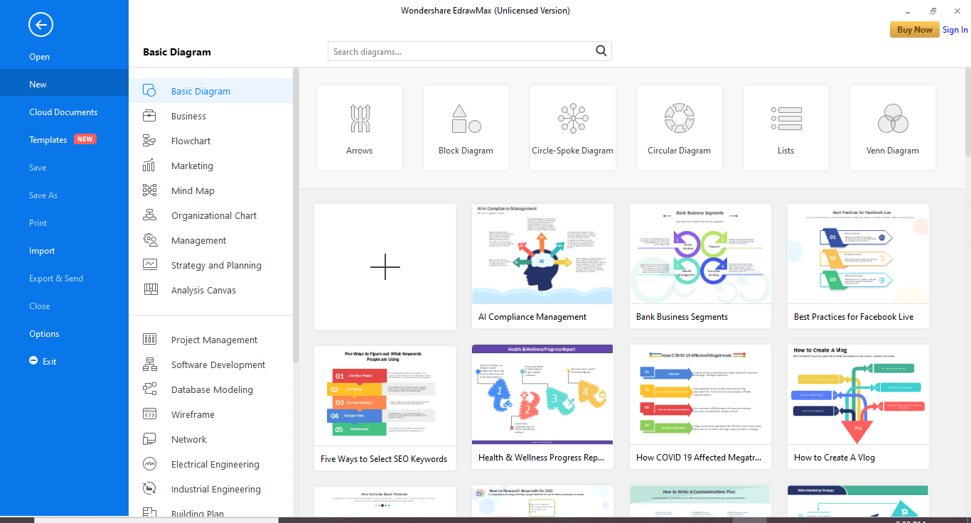
Step 2: Navigate to [New]>[Software Development]>[UML Modeling]
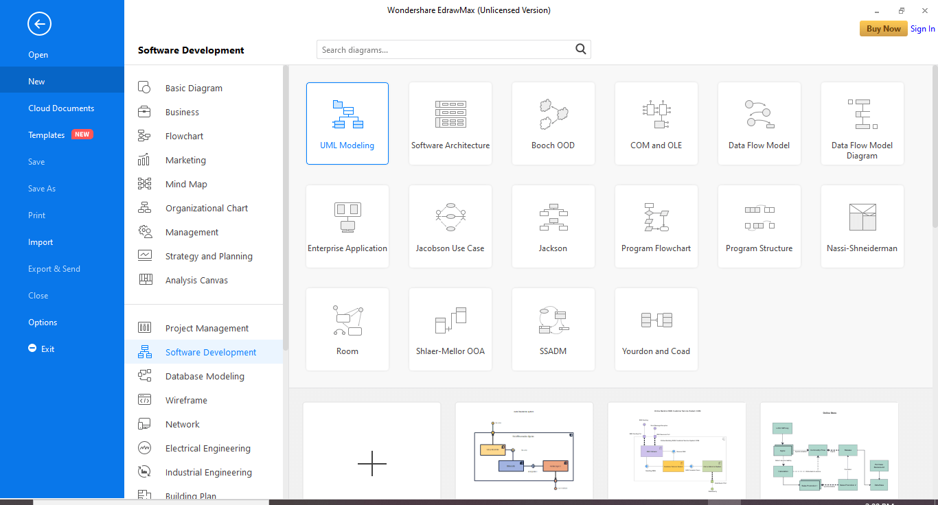
Step 3: You can select any interaction diagram template, including sequence, collaboration, and Interaction diagram, that suits your requirements and modify it accordingly.
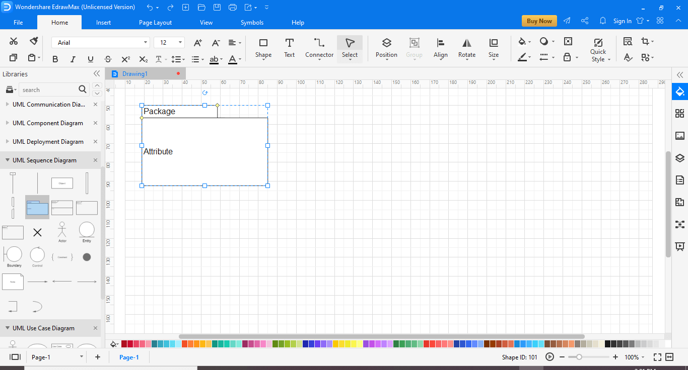
If you want to draw a completely new diagram, then click the [+] sign. You will have an empty canvas like an open playing field, and you can use the symbols and shapes available on the left-hand pane. You can even import libraries in the left menu to customize your UML interaction diagram.
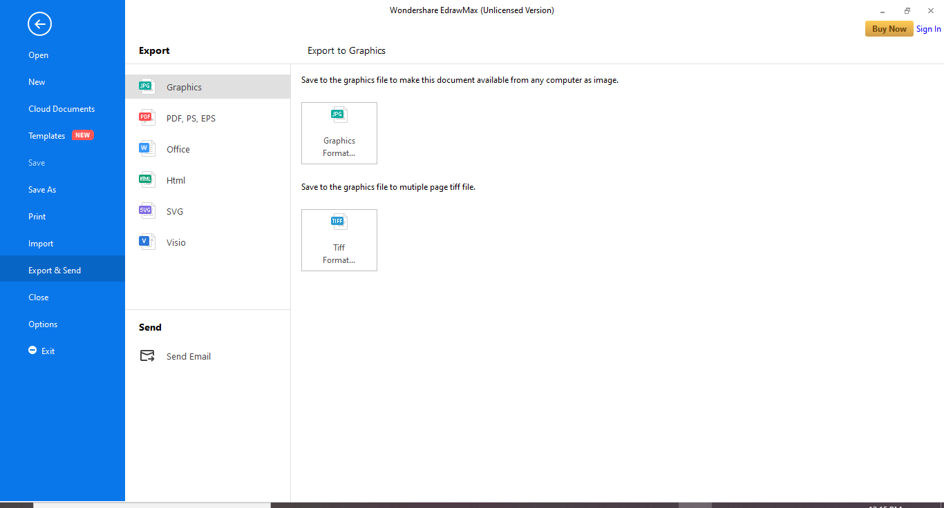
Step 4: Save your diagram. EdrawMax lets you export the file in multiple formats, e.g., Graphics, PDF, editable MS Office file, SVG, and Visio VDX file.

・ Simple alternative to Visio
・ 26k+ symbols
・ 10K+ free templates
・ 10+ AI diagram generators
Following are some things needed in the interaction diagram, and you must take care of these while drawing.
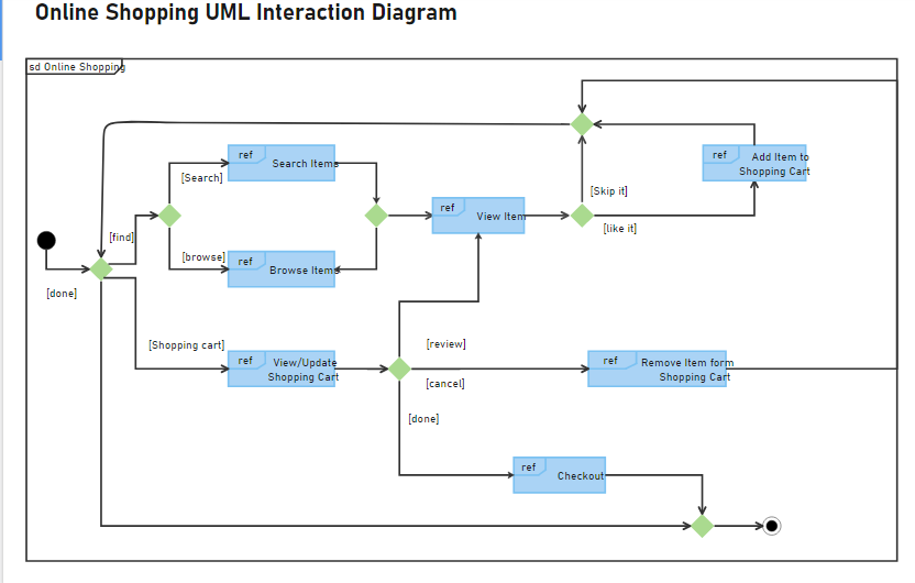
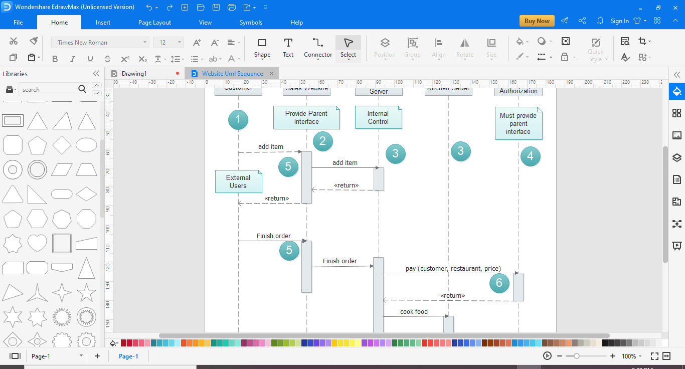
This is an example of an interaction diagram for online shopping. The end-user may search or browse items, add or remove items from the shopping cart, do checkout.


