Object Diagram
Know it All about Object Diagram
The object is an instance of a class at a particular runtime moment with its state and data values. Similarly, an object diagram is an instance of a class diagram. Object diagrams are also known as instance diagrams.
The object diagram depicts the behavioral relationships among class instances during a point in time. This captures dynamic as well as runtime state and modification of the program. It incorporates data values of entities or attributes inside the structure.
An object diagram is an overview of the objects in a program during a particular moment in time, such as the relations together. Object diagrams are used whenever you need to observe and determine the values of attributes and conditions of the object at distinct phases. This can happen at any time throughout the application's performance.
An object diagram can be considered as a unique case of the class diagram. Object diagrams make use of a subset containing attributes from the class diagram and highlight the relationship between instances of classes in the future. They can be useful in realizing class diagrams. They display the same architectural artifacts or attributes that classes do, however they reveal them as a function of runtime.
Object diagrams depict behavior when objects have been instantiated, therefore, we can study the behavior of the system at a particular instant. Object diagrams are essential to represent and understand the functional requirements of a system.
They can be very helpful to study the performance of a complicated process or computation operation. You can create a review of the first phases and the last phases of objects to look at the entire picture.
During the analysis phase of a project, a class diagram describes the structure of a system. Later the team moves on to create a set of object diagrams to serve as test cases to verify the accuracy and completeness of the class diagram.
Object diagrams can also be used to discover facts about specific model attributes, elements, and their links to illustrate specific examples.
UML object diagrams are also helpful in building organization data. The analysis of attributes and the associations between them in the runtime allows for a clear picture of data present in the system and its effects on other components. This is especially relatable in cases where a large amount of data is present and available for modification. An object diagram is an overview of the structure as well as data it can manage.
The purpose of object diagrams can be summarized as:
Object diagram consists of very few notations and symbols. The basic notation of object diagrams is shown here.
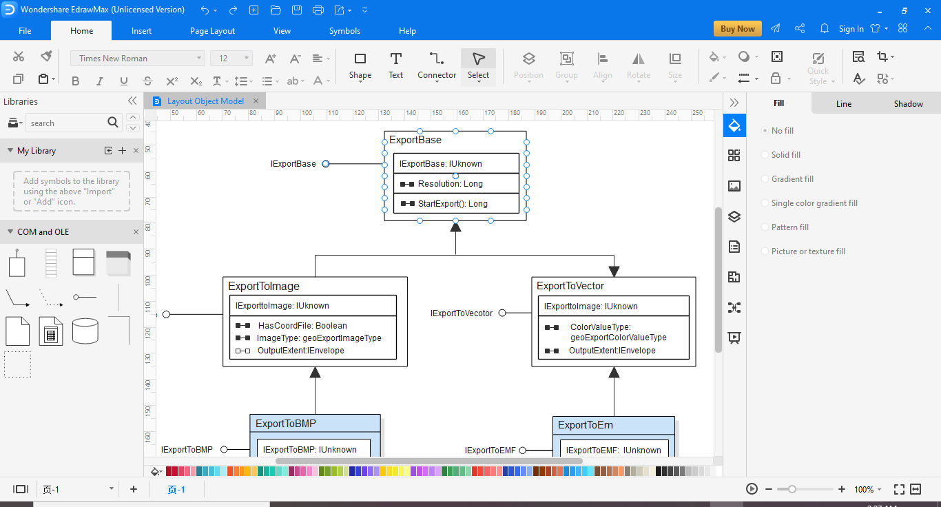
Every object is symbolized by a rectangle. It shows the object name in the top row of the rectangle along with its class underlined and divided by a colon.
Object attributes can be listed in the rectangle in the bottom row. However, unlike classes, object attributes must have values assigned to them at that particular instance of runtime.
Links are instances associated with associations. There are different types of links. They show composition, generalization, and aggregation.
You can use EdrawMax for creating object diagrams easily and within less time. To make the task easier for you, you can use the recommended templates of object diagrams from the EdrawMax template library.
Here are the steps for the creation of object diagrams.
Step 1: Start the EdrawMax program.
Step 2: Go to New>Software Development and select the UML modeling tile.
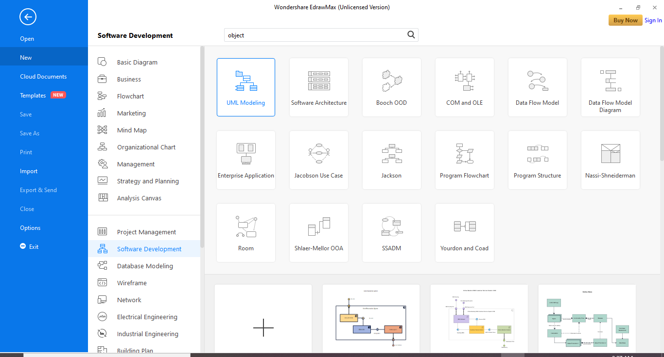
Step 3: In the bottom pane, you can select the template you need and move ahead with personalized modifications.
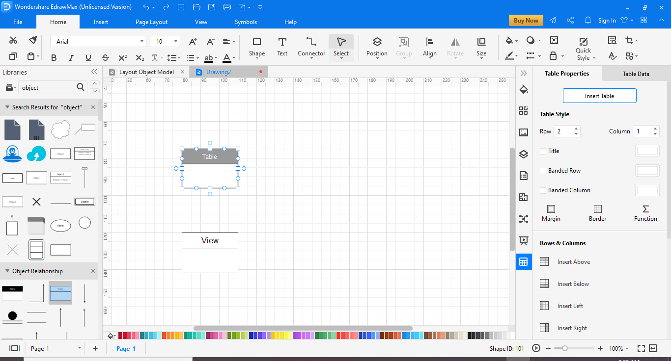
If you want to create the object diagrams from scratch instead. Then here are the steps:

・ Simple alternative to Visio
・ 26k+ symbols
・ 10K+ free templates
・ 10+ AI diagram generators
Object diagram takes its cues from the class diagram. However, you will need detailed analysis and preparation for making a robust object diagram as well. Here are some tips for creating object diagrams.
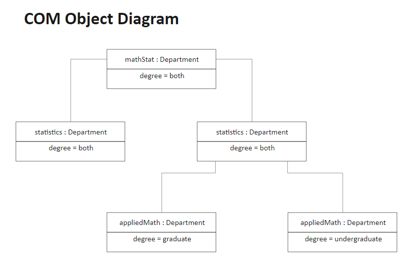
This is an example of an object diagram of different departments in a university. It shows the relation between the instantiated classes and the defined class, and the relations between these objects.


