UML Use Case Diagram
Part 1: What is a Use Case Diagram?
In UML, Use case diagrams are used as a standard notation for modeling real-world objects and systems. A use case is an artifact used in system analysis to identify, define, and organize system requirements. Here, the term "system" is something being developed or operated. Examples of systems are ERP systems, POS systems, etc.
A UML use case diagram is the way to model system requirements for a new software system being developed. They show the expected view and response of the design from the end user's point of view. Use a case diagram is an effective technique for communicating system behavior from the end user's perspective through visualizing externally visible system behavior.
A use case diagram is a simple high-level diagram. It does not show the detail of the use cases or the steps to perform a certain goal. Instead, it only depicts relationships between use cases, actors, and systems.
Part 2: Purpose and Benefit
In UML, the purpose of a use case diagram is to demonstrate the different interaction methods for the end-user. Use case diagrams to help to visualize the functional requirements of a system. These requirements are later translated into design choices and development priorities.
Apart from the interaction model, use case diagrams also help to identify internal or external factors that can influence the workflow of the system. Thus, they provide a high-level analysis of the design from the outside without worrying about the functionality details.
UML use case diagrams are used for many purposes, for example:
- They represent the end-user interaction goals and methods. They show how a user will trigger a response from the system and what is the expected response.
- Use case diagrams are used to define and organize functional requirements in a system along with specifying the context.
- Use case diagrams to represent the basic flow of events through use cases.
- Use cases are also convenient in requirement gathering and documentation.
- In the analysis phase, these diagrams provide an outside view of a system by identifying the system's external and internal factors.
Part 3: Use Case Diagram Components
Actors
Actors are the external users that interact with a system. An actor is a person, an organization, or an external system that interacts with the application being analyzed.
The general guidelines for identifying the actors are:
- Give meaningful and relevant names to the actors. Also, use generalized names to make the modification and presentation simpler.
- To enable quick highlighting of the critical roles in the system, you must place the primary actors on the left side of the diagram.
- External systems are also actors in your use case diagram.
- It is important to note that actors don’t interact with other actors.
- If actors in your system need to interact with each other, you might consider a separate use case diagram to depict this interaction.
- You can also use inheritance for actors.
Use Cases
A use case represents an action, and thus the names should begin with a verb. The general guidelines for use cases are:
- Use logical and descriptive action names for use cases.
- Arrange the use cases in logical order so that the readability of the diagram is enhanced.
- Like actors, use cases can also use inheritance. However, the inheriting use case must be placed below the parent use case to improve clarity.
Relationships
There can be five relationship types in a UML use case diagram.
- Relationship show association between actor and use case
- They represent a generalization of actors
- Extend between two use cases
- Include between two use cases
- They also represent a generalization of a use case.
Systems / Packages
Systems or packages are UML artifacts that group different elements. These groups are represented as file folders in the diagram. However, it would help if you used them sparingly, only when necessary.
Part 4: Tips for Creating Use Case Diagram
Here is the sequence of steps to make meaningful use case diagrams.
Identifying Actors
Actors are external entities interacting with the system. It can be a person, another system, or an organization. Always use general actor names, and you can also use inheritance to classify actors. However, actors mustn't interact with each other.
Identifying Use Cases
An excellent way to identify use cases is to analyze what the actors expect from the system. Then, all the functions done by the system are represented by use cases. You can extend use cases from the top-level use cases depending on the complexity of the system.
After this step, your basic structure of the use case diagram is ready. Now you can improve it using packages and relationships.
Using <>
Identify the standard functionality that can be reused within the system. If your system has two or more use cases that share standard functionality, you can model the common functionality as a separate use case and include it in multiple places. Again, it helps in maintaining the integrity of the system.
Generalize Actors and Use Cases
You can make an actor or use cases with the standard functionality and then use other objects for unique features or functionalities. This is like an inheritance. For example, you can use an actor student and then inherit them as a graduate student and an undergraduate student. You can generalize relationships in such cases.
Optional Functions
you can represent optional functions by extending the relationship.
Part 5: How to Create Use Case Diagram in EdrawMax
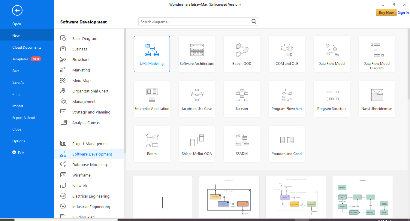
Step 1: Launch the EdrawMax Software
Step 2: On the navigation pane on the left side of the screen, go to Software development>UML Modeling. Choose a free template or click the + tile to create the diagram from scratch.
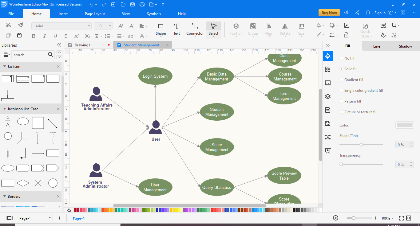
Step 3: When you click on a template, a template will appear on the canvas. You can modify it according to your requirements.
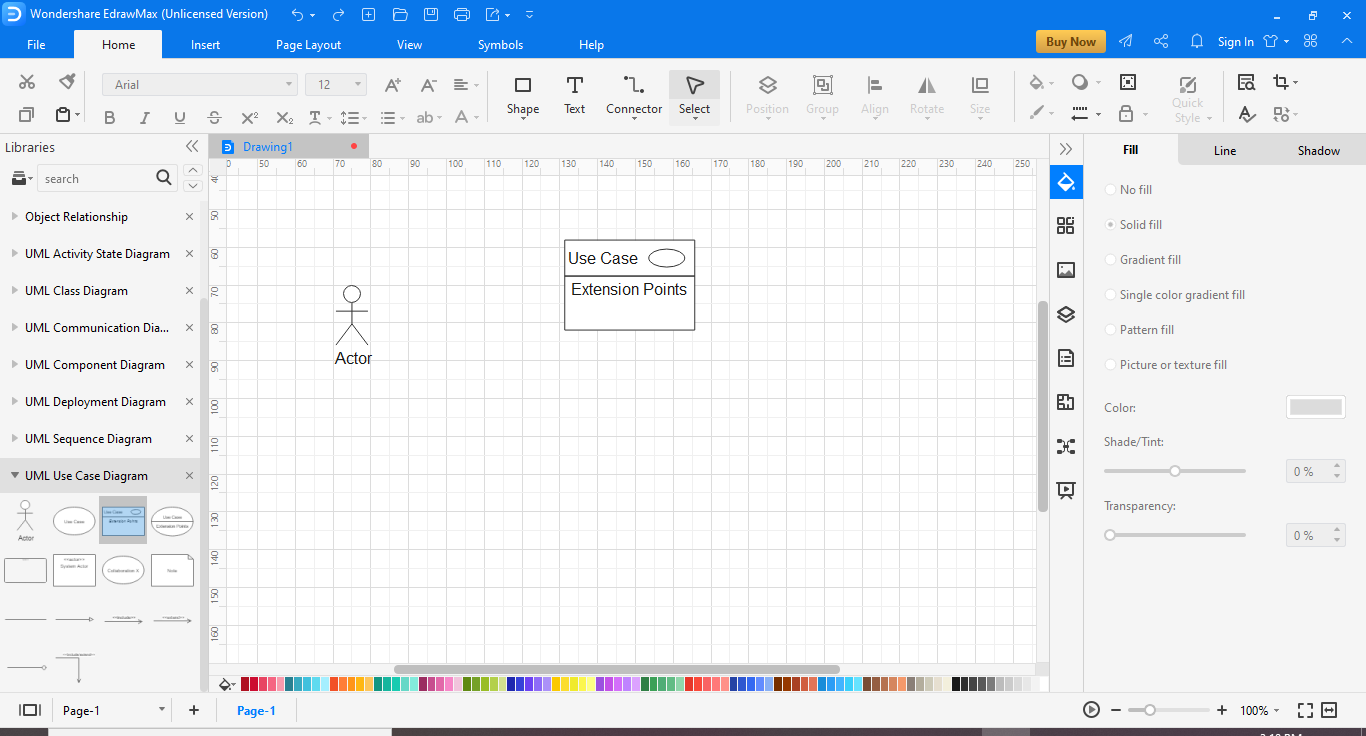
Step 4: To create the diagram from scratch, you can use the symbol library for symbols, drawing, and other visual tools. First, click on the icon next to Symbol Library on the left side of the screen to search for more symbols and icons. Then, scroll down to UML Modelling and select the required library.
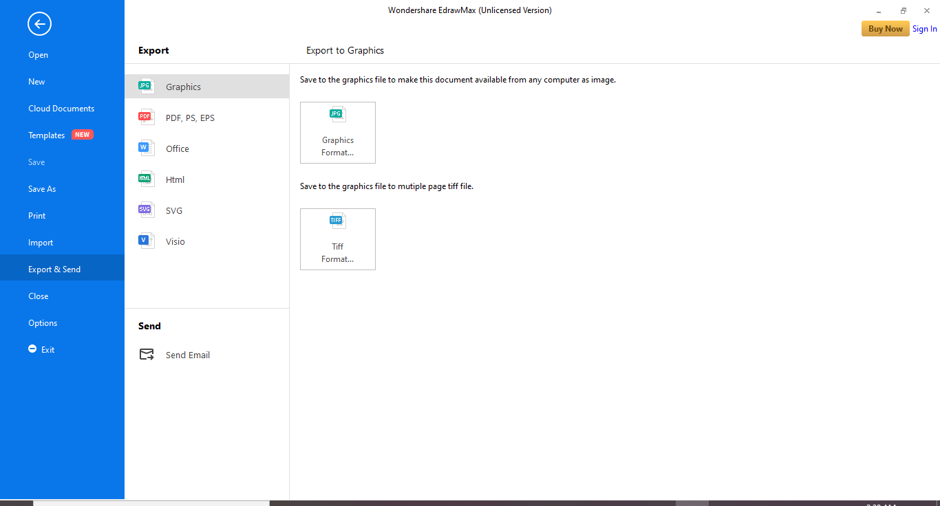
Step 5: Once you are done, save your File. You can also export the diagram to other formats like Excel, Word, or PDF. Click on File and then go to Export.

An all-in-one platform for 210+ diagrams.
・ Simple alternative to Visio
・ 26k+ symbols
・ 10K+ free templates
・ 10+ AI diagram generators


Part 6: Who Need to Use UML Use Case Diagram
- Software developers: Represent software applications using the Unified Modeling Language (UML) notation.
- Software developers: Illustrate and interpret software application relationships, actions and connections.
- Program managers: Show high-level static software structures in presentations and specification documentation.
Part 7: Use Case Diagram Examples
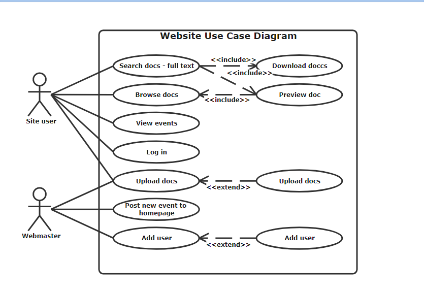
This example shows the use case diagram of a website. It shows two actors, the site user, and the webmaster. The webmaster has more access to the use cases than the site user. You can also notice <
Learn More:
Process Flowchart VS Use Case Diagram


