Relay Wiring Diagram: A Complete Tutorial
Make Your Own Relay Wiring Diagram
EdrawMax Circuit Diagram Maker is able to create circuit diagrams and more electrical diagrams, as well as wiring diagrams in minutes. Give it a try!
Here is the most comprehensive guide you can learn about relay wiring diagrams. We will introduce the basic knowledge of relay and teach you how to draw a customized relay wiring diagram. Don't miss it!
A relay is an electronically generated switch. The internal mechanical shift is operated when the relay normally uses the electromagnet (coil). The power is turned ON for a circuit when relay points open, and the electromagnet is activated.
The relay has contacts in which main contacts are used to shift the circuit and contacts for the loop. A relay contains an alternate voltage trigger; this trigger voltage is when the relay coil operates and normally shifts close to the open and open to the close within the circuit. It is utilized for shifting electronic machines in electronic circuits.
The trigger voltage includes different voltages like 3v, 5v, 12v, 24v, etc. similarly, the image below shows a relay trigger voltage of 5V. It is showing the relay which is shifting the load. The ground is connected through a switch, and +5 volts are supplied to the relay loop. (A switch is a semiconductor or a transistor that carries out the shifting operations). A diode is attached across the relay coil; this diode is known as the Flyback diode. The reason for the diode is to shield the microcontroller from a high voltage spike that the relay coil can create.
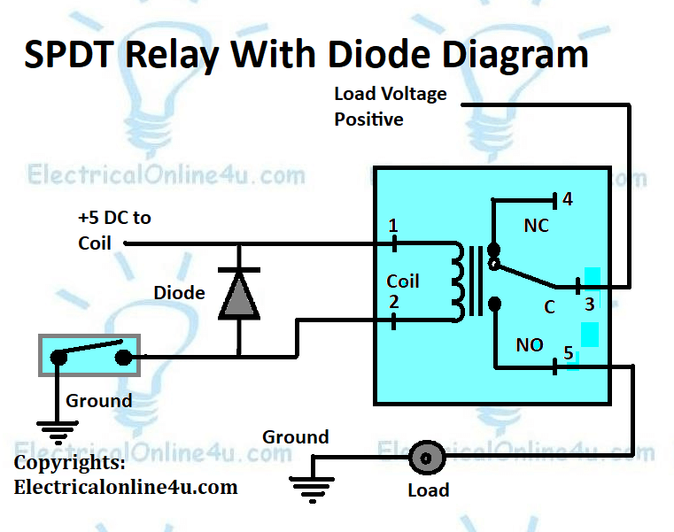
Source: Electricalonline4u.com
The above single shaft twofold through with flyback diode chart shows ground is connected straightforwardly to the load. A positive voltage is associated with the normal pin of the relay, and the supply passes through the normally open contacts. At the point when the relay works, the common and NO will make a closed circuit, and positive supply flows to load.
A small power circuit can handle multiple high current circuits using a relay. It has the following advantages:
Tips: If you are interested in how to draw a electrical circuit, as well as the relay wiring diagram, watch this video to have a try. More about EdrawMax Circuit Diagram Maker.
The difference between a relay and a circuit breaker is that relays act as sensors while circuit breakers break connections. A relay acts as an amplifier that can convert one low voltage signal into multiple high voltage ones. At the same time, the circuit breaker is only capable of disrupting the flow of electricity to the entire circuit.
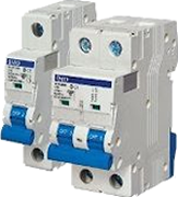
Circult Breaker - a device whicah can:
· Make or break circuit cunder normal conditions either manually or through remote control.
· Break circuit automatically under faulty conditions.
Some types of circuit breakers are Air blast circuit breakers, Vaccum Circuit Breakers, SFG Circuit Breakers, etc. You can notice the circuit breakers near to the transformers. Next time whwn you see a transformer search for the circuit breaker. Mostly will be SFG Circuit Breakers.
Relay - a protective device which senses the faulty conditions in a power system line and initiates the operation ofcurcuit breaker to isolate the faulty part from the rest of the healthy power system. Examples of relays are Over Current relay, Directional relay, etc..
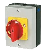
Isolator - or isolating Switch is a device which is used to disconnect a part of the system for maintanace purpose and repairs. Isolator can open a curcuit under no load condition only. If two isolators are connected on either sides of circuit breaker, then the circuit breaker mush be opened before opening the isolator.
After performing maintanance work on the circuit breaker, isolators much be closed first and then the circuit breaker must be closed to bring the system into operation.
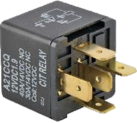
Primary relays indicate electrical ratings for two kinds of contacts: Coil voltage and Internal switching contacts voltage. The relay implies a voltage and ampere ranking of the shifting circuit, which is the rating of the switching contacts that cannot be exceeded.
In double-throw relays, there are two switch specifications of electrical rating. One for the open terminal and the other for the closed terminal. That is N/O: 35A at 14vdc, N/C: 20A at 14Vdc.
They are differentiated by the fact that the 4-pin relay controls only one circuit. On the other hand, a 5-pin relay is a power switch in-between two circuits.
Generally, for a 4-pin relay, there are two types readily accessible; normally open and normally closed. Two kinds of pins are used (85 & 86) to regulate the coil, and 2 pins are used (30 & 87) to switch power on a single board/circuit. In the case of normally open, when the coil is stimulated, the relay will start the power ON for the circuit. For a normally closed, when the coil is initiated, it will shut the power OFF for a circuit.
2 pins (85 & 86) are required by the 5 pin relay to power the coil, and 3 pins are used (30, 87 & 87A) that are supposed to shift power among two circuits. They incorporate both normally open and normally closed connect pins. As soon as the coil is initiated, power will be shifted from the normally closed pin to the normally open pin.
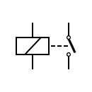
This is the symbol associated with a relay in wiring diagrams.
Finding More In Here: Switches and Relays Symbols
It would help if you wired the relay according to either AC or DC, whatever is being used. The SPDT switch is operational as soon as Pins 85 and 86 have been connected to a coil of any voltage. In the case that the coil is not powered, pins 30 and 87a are connected. As soon as the voltage is applied to the coil, pins 85 and 86 while pins 30 and 87 connect. Pin 30 is typically connected via a fuse to the positive terminal of the source. The LOAD (lights, fan, etc.) is connected through pin 87 to the negative terminal of the power source. Once this has been done, connected pin 86 to the positive terminal of the source as well. Lastly, connect pin 85 to one of the posts of a push-type switch, keeping in mind that the remaining post of the switch should be grounded. This is how a relay is wired commonly.
The diagram above is the 5 pin relay wiring diagram. There are different kinds of relays for different purposes. It can be used for various switching. Relay can be the best option to control electrical devices automatically. 5 pin is compromised of 3 main pins and an SPDT (single pole double throw). So, a single pole double throw has a mutual point and two other points (Normally Closed and Normally Open). This means if we want to shift anything from a single pole double throw relay, we need to use a common and normally closed pin. And in case we want to turn on the light bulb, we need to use the common and normally close pin.
Relays are primarily utilized for remotes shifting and for high voltage or high current switching. They are especially significant because they can handle these high voltages and flows with just a little voltage or current. Another significant use is for AC electrical cables.
We highly recommend EdrawMax for making your relay diagram. There are tons of templates that you can choose from and the right symbols that you require for making the diagram.