Project Management Network Diagram Complete Guide
Edraw Content Team
Do You Want to Make Your Project Management Network Diagram?
EdrawMax specializes in diagramming and visualizing. Learn from this network diagram project management complete guide to know everything about the network diagram project management. Just try it free now!
It's easy for a project manager to become perplexed at the start of a project. The most common source of difficulty is determining which activities should be prioritized. It is critical to establish a logical relationship between the tasks so that everyone understands the project's nature and sequence. It's also critical for the core project team to quantify the interdependence between activities to operate as efficiently as possible and meet the project's objectives. As a result, specific preparation is required while determining the dependencies.
Project managers require a network diagram project management tool to graphically represent a project's activity and events. This project management network diagram guide will teach you how to create a project network diagram using EdrawMax. In addition, we will explore the types of project network diagrams. Without further ado, let's get started.
1. What is a Network Diagram in Project Management
A project network is a graph that depicts the activities, timeframe, and interdependencies inside your project. However, a network diagram is a graphical representation of a project's activities and events. It illustrates how each activity in the project links to others, the order in which activities must be completed, and the importance of executing some tasks before others.
Network diagrams also make it easier to analyze the effect of early or late starts or finishes, offer information on resource allocation, and allow managers to conduct "what if" scenarios. Managers can use this data to check on the status of the plan, review progress, and weigh alternatives.
![]()
Each activity must have a start and an end, and all other activities must fit within these constraints. There are various techniques to design a network diagram, but the arrow diagramming method (ADM) and the precedence diagramming method (PDM) are the two most used methods. Most project managers nowadays design their network diagrams using the precedence diagramming method.
A project network diagram illustrates a project that uses a sequence of related arrows and boxes to show the interrelationships between the project's activities. The activity description is represented by boxes or nodes, whereas arrows show the relationship between the activities.
2. Types of Project Network Diagrams
When drawing your project network diagram, you must choose the successor or predecessor for each activity. After this, you have to create a dependencies chart. However, before creating the diagram, you have to generate a logical connection between the activities. Therefore, a project manager must analyze these dependencies before creating the diagram. Nowadays, you can use several network diagram software to loop through activities. Notwithstanding, a project network diagram comprises the arrow and the precedence diagramming method. It's essential to have a basic knowledge of these two types of project network diagrams.
2.1 Arrow Diagramming Method (Arrow Network)
An Arrow network diagram is a network diagram where activities are displayed using arrows and connected using nodes. The arrow tail represents the beginning of the activity, whereas the head is the end of the activity. The arrow length is directly proportioned to the activity duration.
An arrow network only displays the finish-to-start relationships between activities. Each activity starts and ends at a node; the node represents the starting or ending of an activity in a sequence. An activity starting node is known as I-node, whereas the ending node of an activity is called J-node.
Relationships between activities usually require a dummy activity to represent these activities correctly. Unlike the arrow length, the dummy activities don't have any duration. However, it establishes complex relationships between activities that cannot be established. In most network diagrams, dotted lines represent a dummy activity.
![]()
Pros of Arrow Diagramming Method:
-
Visual picture of the project for all the stakeholders that participate in the business in any way.
-
It lays out the steps and required tasks necessary in a project and the order they need to be executed.
-
It shows complete time frame important deadlines and reporting dates of each step.
-
It helps in tracking dependencies, monitoring quality of work and chasing potential bottlenecks.
-
This method makes it easier to figure out a sequence of tasks and duties in the project, allowing project managers and their subordinates to deliver in an effective and efficient manner.
Cons of Arrow Diagramming Method:
-
Mapping out an arrow diagram method is time consuming and requires high costs, and talent to produce.
-
Arrow diagram method does not give every little detail about the project and the tasks that it entails.
-
It's quite complex to scale the timeframe of the tasks.
2.2 How to Create an Arrow Diagramming Network Diagram
Let's look at the data below. It contains six activities starting from A to F with the predecessors of every activity.
|
Activity |
Predecessor |
|---|---|
|
A |
- |
|
B |
A |
|
C |
A |
|
D |
B |
|
E |
C |
|
F |
D,E |
If you want to create the arrow diagram for this example, you need to draw a node that illustrates the start of the project. From the diagram below, node 1 represents the start of the project. The numbering of the node doesn't have to start with 1; you can use whatever you want.
Activity A doesn't have any predecessor, so you draw an arrow initiating the beginning of the node and ending at 2. At node 2, activity A has ended and likewise with other numbers. Similarly, you can draw activities D and E. Since activity F has two predecessors, it requires two arrows to indicate the originating point where D and E end (node 5). However, node 6 represents activity F ending and also terminates the project.
In ADM:
- The tail of the arrow represents the beginning of the action, and the head of the arrow represents the end.
- The arrow length usually indicates how long the activity will last.
- Each arrow links two "nodes" or boxes. The nodes are used to mark the beginning and end of a sequence of activities. The "I-node" is the initial node of an activity, while the "J-node" is the last node of a series.
- An ADM diagram can indicate the only connection between nodes and activity is "finish to start," or FS.
2.3 Precedence Diagramming Method (Node Network)
The precedence diagramming diagram represents activities using nodes that are linked using arrows. The arrows represent the relationships between these activities. Unlike the arrow diagramming network, the precedence diagramming network can represent four different types of relationships. These include Finish to Start, Finish to Finish, Start to Finish, and Start to Start.
Pros of Precedence Diagramming Method:
-
PDM is a better tool to more accurately develop the project schedule as compared to ADM.
-
This diagramming method clearly speaks about the dependencies clearly stating everyone's duties and responsibilities.
-
It helps to evaluate critical activities and helps to focus on them.
-
In PDM required time is labeled alongside the arrows, which helps the stakeholders to scale the timeframe of the project.
-
The PDM also shows the results and impacts occurred due to changes in the schedule.
-
It shows activities as flow lines and not points in time.
Cons of Precedence Diagramming Method:
-
Updating and managing the changes can be a troublesome task and is time consuming.
-
It is more complex to update and manage due to less network details.
2.4 How to Create a Precedence Diagramming Network Diagram
Let's look at the following data to illustrate how you can create a precedence network diagram. The table below shows six activities, starting from A to F. The predecessors for every activity are also shown in the table.
|
Activity |
Predecessor |
|---|---|
|
A |
- |
|
B |
A |
|
C |
A |
|
D |
B |
|
E |
C |
|
F |
D,E |
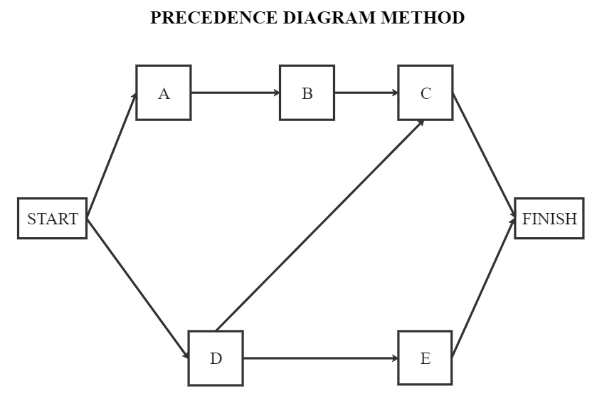
To create the precedence diagram, you must draw the first box to represent activity A (starting point). The next step is to connect B and C, which have A as the predecessor. Therefore, two boxes must connect B and C before connecting to activity A. Furthermore, you need to draw a box for D and E that connects to activities B and C, respectively. Finally, you will draw another activity box for F while connecting it to D and E activities.
In PDM:
- Start to Finish (SF) - It is an uncommon dependency where one activity can only finish one another starts.
- Finish to Start (FS) - The activity cannot start before another finish.
- Finish to Finish (FF) - Occurs when two activities must finish together.
- Start to Start (SS) - Occurs when two activities can start simultaneously.
2.5 Differences between the Arrow and Precedence Diagramming Methods
So far, it is easy to identify some critical distinctions between both types of project network diagrams.
- The precedence diagramming method is more straightforward and widely used than the arrow diagramming method.
- You don't require any dummy activity to represent a complex relationship in PDM. However, you need lines to display relationships. In an arrow diagram network, you need dummy activities to represent complex relationships.
- n the arrow network, you only have two relationship types (Start to Finish), unlike PDM, which has four types.
3. Preparations Before Drawing Project Network Diagrams
Before starting your project network diagram, you need to know the chronological order these activities must be executed. You have to define the network diagram's start and ending points in it. In addition, you need to use your arrows from left to right when plotting your diagram. The diagram should automatically follow such a pattern.
It's vital for the project network diagram to remain as straightforward as possible and easy for people to discern. Therefore, there shouldn't be any clutter within the page with arrows crossing one another. Any arrow used for directional purposes must be straight. However, the duration for a particular arrow represented must not be based on its length.
Drawing a network diagram requires a lot of pre-planning to achieve the best outcome. Here are a few things to prepare yourself before drawing project network diagrams.
Step #1 Design a Predecessor Table
A predecessor table represents a table that displays the activities in one column and records the preceding activities that came before them in the other. For example, here's the predecessor table. Keep in mind that this is a predecessor table for an arrow diagramming method, in which arrows indicate activities and nodes represent milestones.
|
Activity |
Description |
Predecessor |
|---|---|---|
|
0 |
Kick-off meeting (Start) |
- |
|
1 |
Identify market |
- |
|
2 |
Design website |
- |
|
3 |
Create Content |
- |
|
4 |
Submit Content |
3 |
|
5 |
Edit Content |
3 |
|
6 |
Build content |
2, 4 |
|
7 |
Develop marketing |
1 |
|
8 |
Marketing push |
7 |
|
9 |
Test website |
6 |
|
10 |
SEO work |
5 |
|
11 |
Launch website |
8, 9, 10 |
Step #2 Identify Activities for the Network Diagram
You must first plan your tasks before putting pen to paper. You don't want to get started on your project network diagrams to discover that you've forgotten to include some key activities. Task dependencies exist in which tasks cannot begin or terminate until another activity has begun or ended. Using a work breakdown structure, identify them and divide the project into phases. Then you may begin creating the network diagram and determining the critical path.
Step #3 Sketch a Draft of Your Network Diagram
On a more fundamental level, begin by sketching your project network diagram on paper. You can then delete and rearrange elements until you've created the most efficient schedule network diagram possible.
Consider font once you've completed the final design. Different typefaces can be used to draw attention to specific areas of the diagram and make your project network diagrams simpler to read. A note or key at the bottom will also assist the reader in comprehending the information.
Step #4 Review Your Sketch
You might want to review your diagram again to ensure everything is positioned correctly. You can use the predecessor table to check if the activities match their order and if the dependent activities are depicted. Once everything looks good, you can start your main drawing using any software. With this, you minimize the time you would have spent on software trying to figure out how the diagram should be.
Step #5 Drawing Your Network Diagram
Lastly, you need good software to capture your sketched work. While there are different software, you might want to consider using EdrawMax. You can use the standalone program or the web application. With EdrawMax, you can start from scratch or use a network diagram template to create your drawing.
3.1 Project Network Diagram Requirements
As previously said, creating a network diagram involves thorough planning. Before creating a network diagram, the following information should be available.
- The project's start and finish points must be specified and outlined.
- There must be a list of all project activities.
- It is necessary to make an accurate estimate of the duration for each activity to complete.
- It is vital to identify dependencies.
3.2 Best Practices for Project Network Diagrams
The following are best practices to follow when creating a project network diagram. When done correctly, network diagrams can provide several advantages. Let's look at some of the best practices for creating a network diagram project management.
- Use internationally recognized and acknowledged standard network diagramming symbols.
- If you're going to use different symbols, ensure they are defined.
- Use straight arrows at all times.
- Avoid crisscrossing arrows.
- Use the smallest number of dummies possible.
- Arrows should be utilized in a left-to-right direction.
- Use only one starting and ending point.
- Make use of tools to improve precision and clarity.
- Ensure your diagram contains up-to-date and relevant information.
- The network diagram must have the appropriate level of detail.
- Ensure the information or data for creating the diagram is accurate.
4. How to Draw a Project Network Diagram in EdrawMax
A project network diagram is a diagram that connects activities and displays all project tasks, durations, logical relationships, and activity interdependencies. Project schedule network diagram is another name for project network diagram. A project network diagram comprises blocks, circles, lines, dotted lines, arrows, and other symbols that allow you to see relationships between activities quickly. Let's look at the steps to draw a project network diagram in EdrawMax.
Step1 Open EdrawMax and Login
The very first step that you need to follow is to install EdrawMax in your system. Go to EdrawMax Download and download the network diagram software depending upon your operating system. If you need remote collaboration with your office team, head to EdrawMax Online and log in using your registered email address.
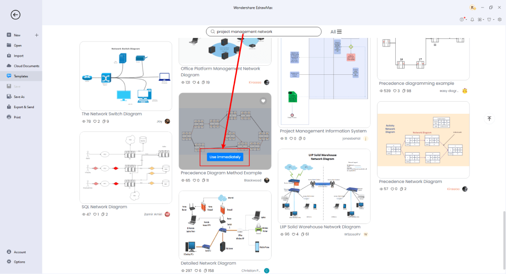
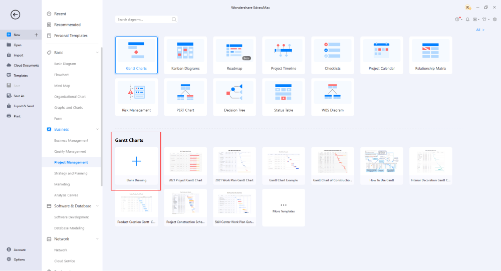
Step2 Select a Template
After launching, the Home screen opens by default. Head to the Template bar and search for network diagram project managements in the search box. In-built templates specific to your search will appear on the screen. EdrawMax features a large library of templates. We have more than 25 million registered users who have produced thorough Templates Community for each design. Select the template you like and click Use Immediately to open it in a new window for customization.
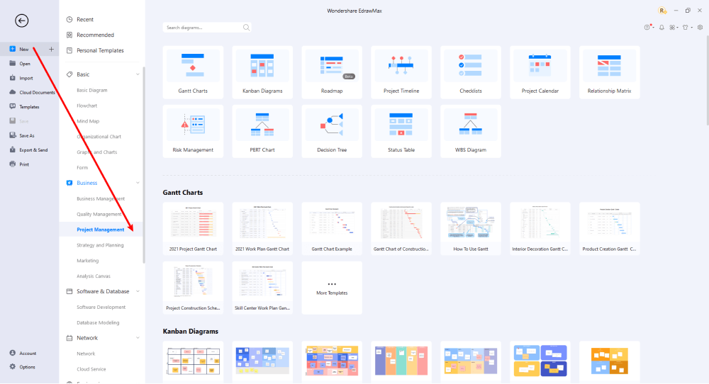
Step3 Create From Scratch
From the EdrawMax homepage, you will find the '+' sign that takes you right to the canvas board, from where you can start designing the project network diagram from scratch. Coupled with your technical expertise, you can use a wide range of symbols to draw a detailed project network diagram.
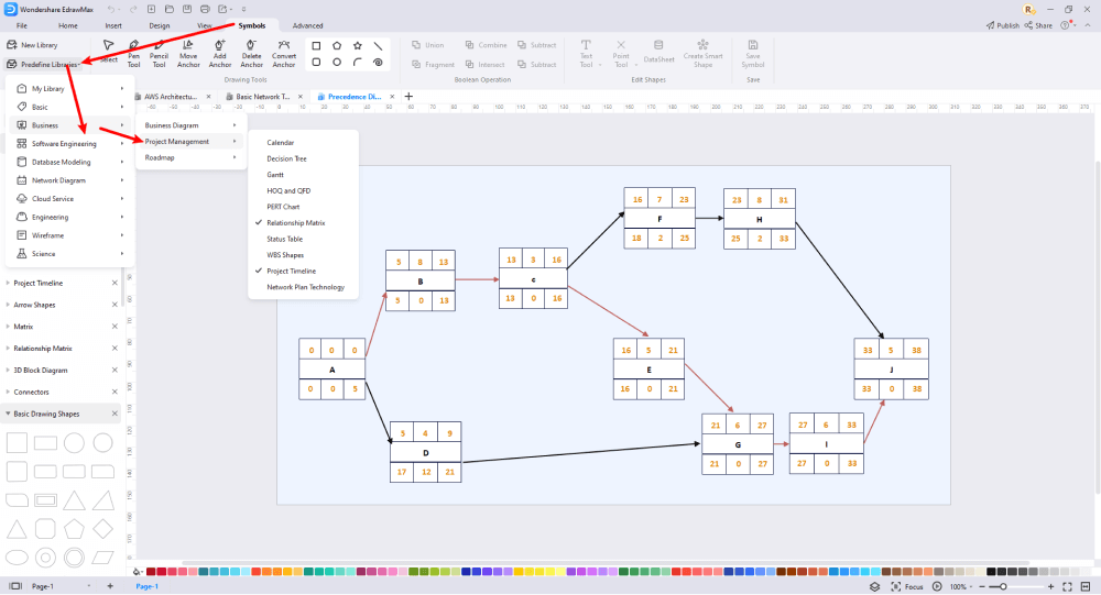
Step4 Select Symbols
EdrawMax includes a large number of symbol libraries. You may quickly build any type of diagram with over 26,000 vector-enabled symbols. If you can't locate the symbols you need, you can easily import some images/icons or build your own shape and save it as a symbol for later use. Simply go to the 'Symbols' part of EdrawMax and select the 'Predefined Symbol' section from the top toolbar. Hundreds of symbol categories are accessible for you to utilize and incorporate into your project network diagram.
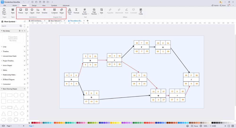
Step5 Add Components
After you have sketched out the basic pieces, you may customize the typefaces, colors, and other details by selecting the right or top menu to make your network topology design more visually appealing. Also, feel free to draw ideas from other layouts on Templates Community and transfer some of the photos or features that you think would go well with your project network design.
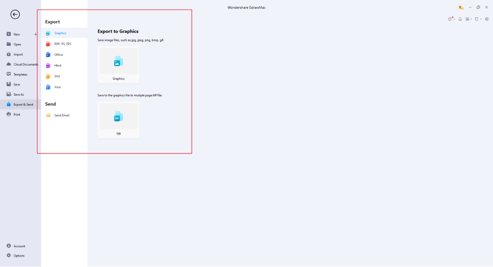
Step6 Finalizing the Plan
Once your project network diagram is ready, you can collaborate with your team to consider their opinion using the Cloud-base files. EdrawMax allows up to 100M free cloud storage. It supports files in several formats, including HTML, PDF, Graphics, Visio, Microsoft Office, etc. It is not a complicated process to create a project network diagram in EdrawMax. You can take a template and continue customizing it to suit whatever design you want. EdrawMax has several templates with fantastic designs for a project network diagram for your organization.
Basically, it is simple to create a project network diagram in EdrawMax, just grab a template and keep customizing, drag and drop professinal symbols to make your plan better. If you are still confusing about how to make a project management network diagram in EdrawMax, you can find more tutorial videos from our Youtube
6. Project Network Diagram Examples
Different project network diagram examples and templates are available on EdrawMax. You may discover project management examples and templates to represent information graphically. It is also possible to construct more professional network diagrams using free templates from EdrawMax. Just click the image to download EdrawMax, and download the templates accordingly. Then double click to open the templates and customize as your prefer. Or open the templates from EdrawMax Templates Community, and duplicate the templates.
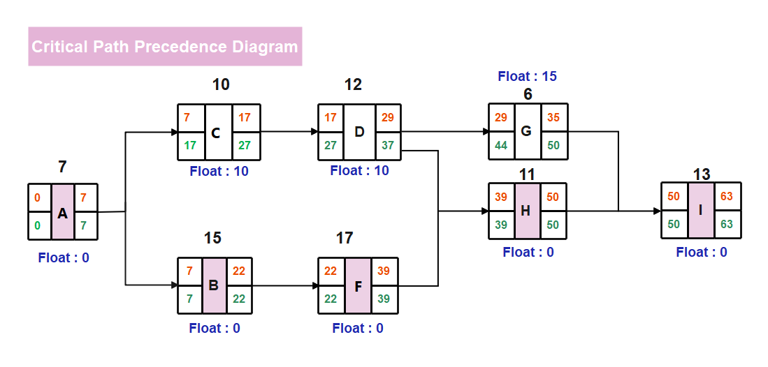
Example 1: Critical Path Network Diagram
The critical path analysis visually represents the sequences of tasks required to accomplish a project using a network diagram. After these work sequences or pathways have been determined, the duration of each is calculated to determine the critical path that defines the project's overall duration. In EdrawMax, you will find several critical path network diagrams for your project.
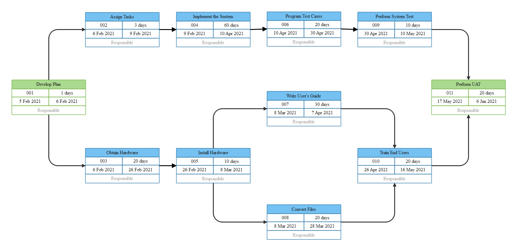
Example 2: PERT Network Diagram
A Program evaluation review technique (PERT) diagram is a tool that provides a visual illustration of a project's timeline. The PERT network diagram example displays the primary stages of developing a plan, beginning with the hardware and allocating tasks to team members. After completing the hardware installation, the testing team will proceed to produce a user guide to improve customer satisfaction. The project plan PERT chart can be divided into individual tasks for analysis. Use EdrawMax or EdrawMax Online pre-defined templates to generate eye-catching chart diagrams instead of starting from scratch when developing a PERT chart example for multiple teams.
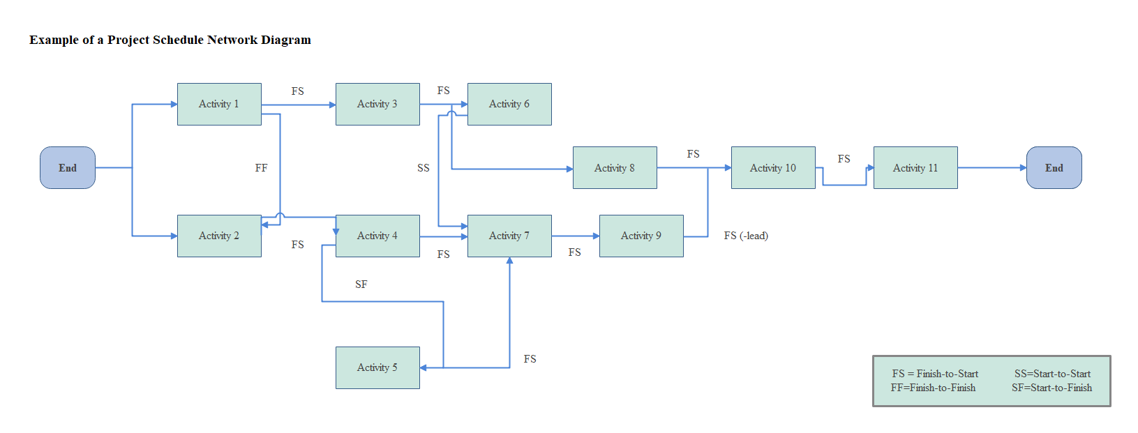
Example 3: Project Schedule Network Diagram
A project schedule network diagram depicts the sequential and functional relationship between tasks in a project environment. The accurate representation of the sequence of activities and tasks is essential for this project. A project network diagram is most commonly shown as a chart with a sequence of boxes and arrows. This network diagram tool is used to plan out the project's timetable and work sequence and track its progress through each stage - from start to finish. A network diagram effectively displays the breadth of the project since it incorporates the big tasks that must occur throughout the project's length.
6. Free Network Diagram Tool
There's only one way to determine whether a project network diagram is right for you: give it a shot. Fortunately, there are a plethora of free internet tools for creating network diagrams. EdrawMax project network diagram tool is one of the best premium software available online. It's a professional all-in-one tool for creating a wide range of diagrams and graphs, including network diagrams, maps, flow charts, process diagrams, and floor plans. It also includes a model and example gallery. Diagrams and charts are helpful in every field because they convey information quickly, facilitate analysis, and may be used at any point in the process. In addition to facilitating the production of mind maps, software architecture models, and website design, the tool allows users to share the models they produce with their team.
Some of the key features of EdrawMax include:
- EdrawMax contains various complicated layouts that allow users to create entity-relationship diagrams quickly.
- It can be used for various things, including idea maps, flyers, banners, and business cards. In terms of general design, the capabilities are wide.
- It comes with numerous templates that can be used for various purposes. You can also create, save, and share your customized templates.
- EdrawMax works on Linux, Mac OS, and Windows.
- The user interface is easy to navigate, allowing even a novice to search for things.
- Since data import is automated, it is simple to visualize all data.
7. Final Thoughts
Creating a project management network diagram as a sketch before drawing can help you comprehend the relationships between activities much more readily, no matter what project you're working on. It's critical to invest in a good diagramming tool to assist you in creating network diagrams. You can quickly draft these diagrams using pre-made templates and shapes, and you'll be able to readily share them with your team, especially if you go with a cloud-based solution.
Although you might find several network diagram project management software online, none beats EdrawMax. The moment you start using EdrawMax , you will realize that the tool comes with several amazing features that ease your efforts in creating the network diagram project management and help you share the designs using the easy sharing option. With EdrawMax, you can export your file into multiple formats, and share your works on different social media platforms, like Facebook, Twitter, LinkedIn, and Pinterest. All in all, EdrawMax is a wonderful tool that caters to all of your designing and drawing needs.

Project Network Diagram Complete Guide
Check this complete guide to know everything about the project network diagram, like types, examples, and how to make a network diagram project management.
You May Also Like
GCP Architecture Diagram Complete Guide
Knowledge
AWS Architecture Diagram Complete Guide
Knowledge
WAN Diagram Complete Guide
Knowledge
LAN Diagram Complete Guide
Knowledge
MAN Diagram Complete Guide
Knowledge


