System Sequence Diagram: A Complete Tutorial
Know it All about System Sequence Diagram
The UML diagram is used to model the relationship between the classes and their components in a general way. It provides you the general blueprint to represent your software architecture. The UML is of two types the structural UML and the behavioral UML. In this article, we will see the System Sequence diagram (SSD) that is the type of behavioral UML diagram.
The System Sequence Diagram, aka SSD, is the sub-type of the sequence diagram that shows us the input and output events. The system sequence diagram illustrates the sequence of use cases. These use cases are the events caused by external actors. It defines their order and the events occurring inside the system.
Source: github
These diagrams are made from the success of one possible use case and then further made by using the other use cases. In the system sequence diagram, the system is considered as the black box. They are used as input for object design.
The System Sequence Diagram (SSD) tracks how the functions and the use case functions are performed inside the system. You use these diagrams to model your software in concern with how the system interacts with the events.
This diagram is used to create a blueprint derived from the main success scenario, and then you further design by seeing other cases and scenarios.
Some of the elements that are used in the use case diagram are also as follows here. The essential elements of the system sequence diagram are.
In a traditional UML, the box depicting a title represents the class or an object but, in System Sequence Diagram, this shape represents the system as the black-box. The black box is a system that is not illuminated to the outside world because they contain inner processes.
These are the external entities that interact with our system, and the system is created by keeping actors in mind. The interaction can be like interacting with the cashier, customer retrieving amount from the ATM or anything. They are the stick-like figures in the diagram.
The interaction or communication of an actor or system to the system is an event. Then with the specific event, the system performs the specific task. These events are generated in a sequence or a specific order. The dashed lines aka, the lifelines, are the events in the system sequence diagram. These lines start from the rectangle shape o with an actor.
| Sequence Diagram | System Sequence Diagram |
|---|---|
|
In the Unified Modeling Language (UML), the sequence diagrams depict the relationship between the actors and objects in a system with respect to time. The sequence diagram shows the control flow of these relations and how the system works regarding these relationships of objects and the actors. When the objects become so complex in a system design, this diagram is made to model the control flow and relationship between actors and objects. |
The System Sequence Diagram assumes the higher abstraction level by visualizing the control flow of the system and the actor. Visualizing the interaction between the classes and objects using a sequence diagram is not part of this analysis. |

・ Simple alternative to Visio
・ 26k+ symbols
・ 10K+ free templates
・ 10+ AI diagram generators
Step 1: Download and install EdrawMax on your PC. Alternatively, you can use EdrawMax Online to create diagrams instantly.
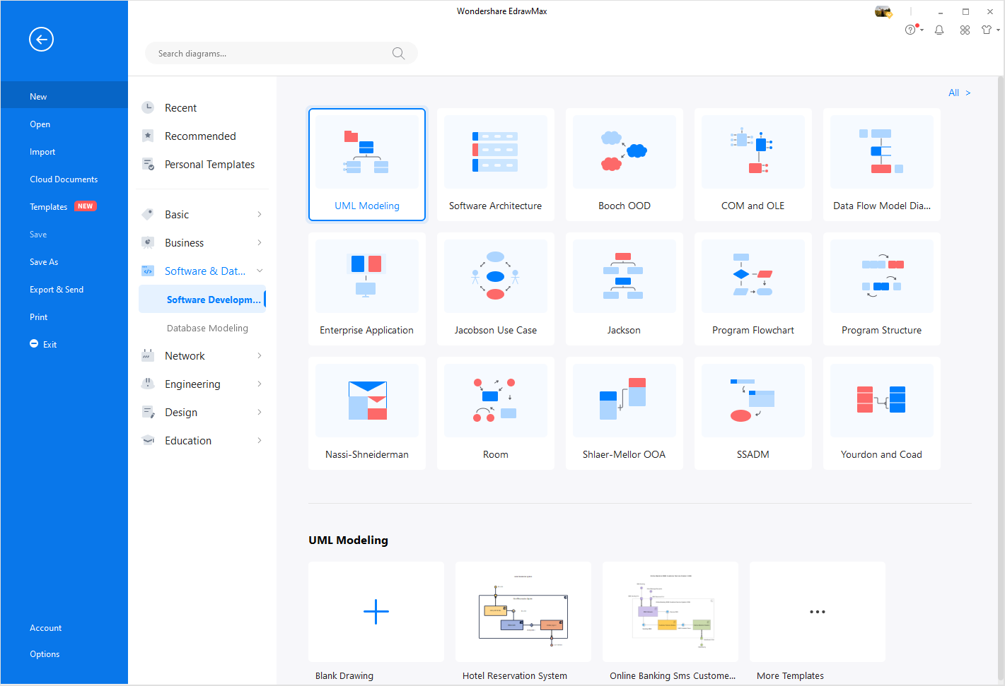
Step 2: Navigate to [Software & Database] > [Software Development] > [UML Modeling]. Here you can choose to open a blank drawing page to start from scratch. Or you can select one of the templates from the gallery.
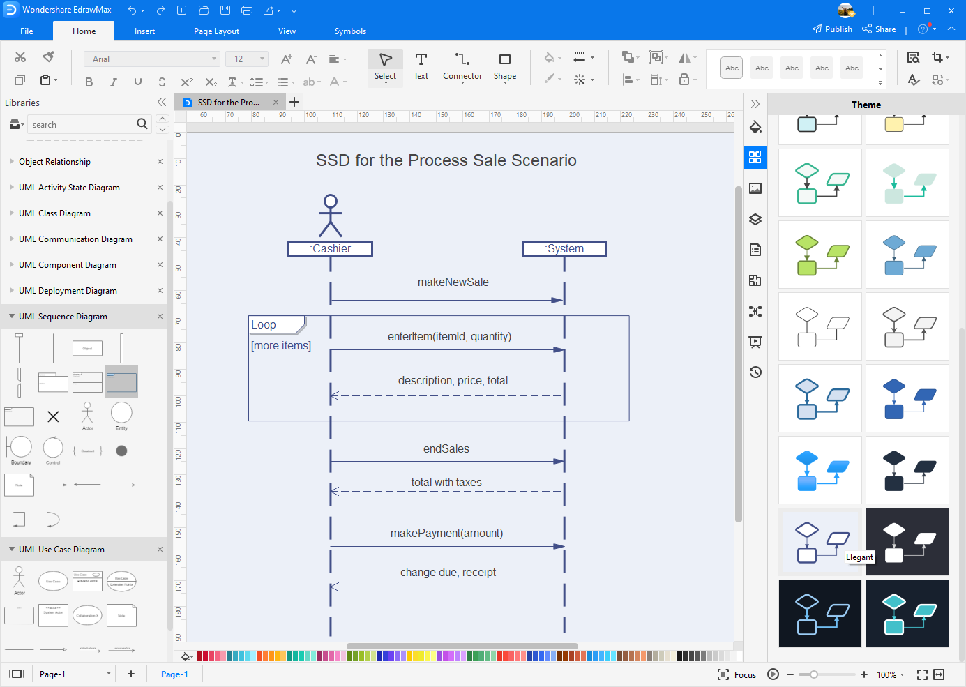
Step 3: All the symbols for drawing a system sequence diagram are on the left panel. You can find more symbols in the symbol libraries. Now, drag and drop the symbols onto the canvas and start diagramming with EdrawMax!
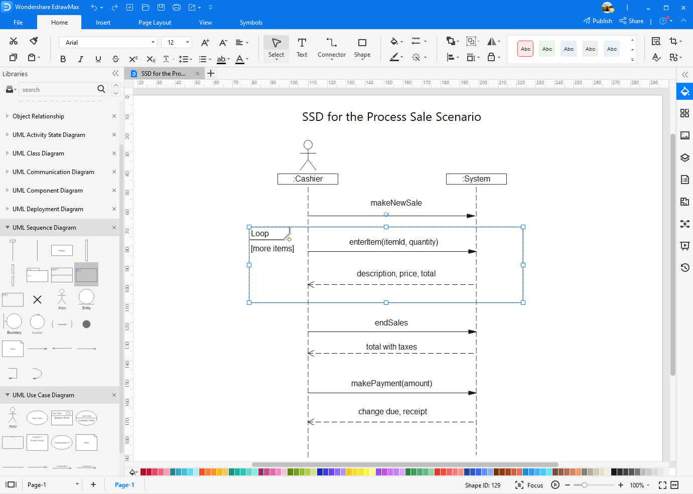
Step 4: With all the styling and formatting tools in EdrawMax, you can change the styles of your diagram as you like.
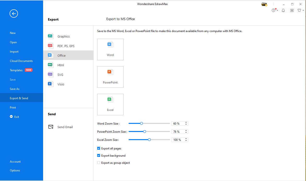
Step 5: After your daigram is completed, go to the [File] tab and click [Export & Send]. You can choose to save and download your creation in difference file format, like PDF, JPG, PNG, SVG, Visio, Excel, Word, PowerPoint and HTML.
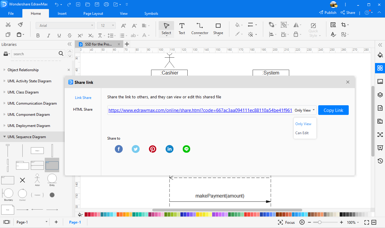
Step 6: Click the [Share] button on the top-right corner of the software and select the ways of sharing your diagrams.
You cannot fully understand the theory of something until you also understand the practical implementation of something. This section will illustrate to you the practical implementations of the System Sequence Diagram.
Source: www.sciencedirect.com
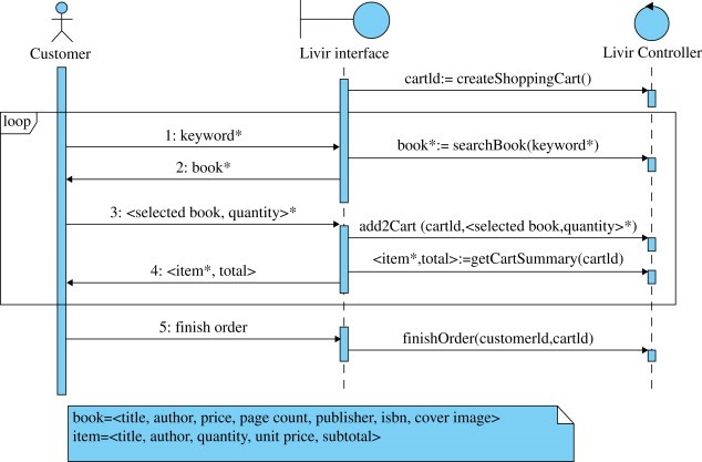
It is the system sequence diagram of a book store. The actor is the customer that passes his information to the interface just one time. The interface passes this information every time as an argument to the controller each time a system command or query needs that information.
See, when the methods add2Cart, getCartSummary, and finish order are called, the interface passed the cartId to the controller three times. Now, we get the developers have made the shifts from analysis to design.
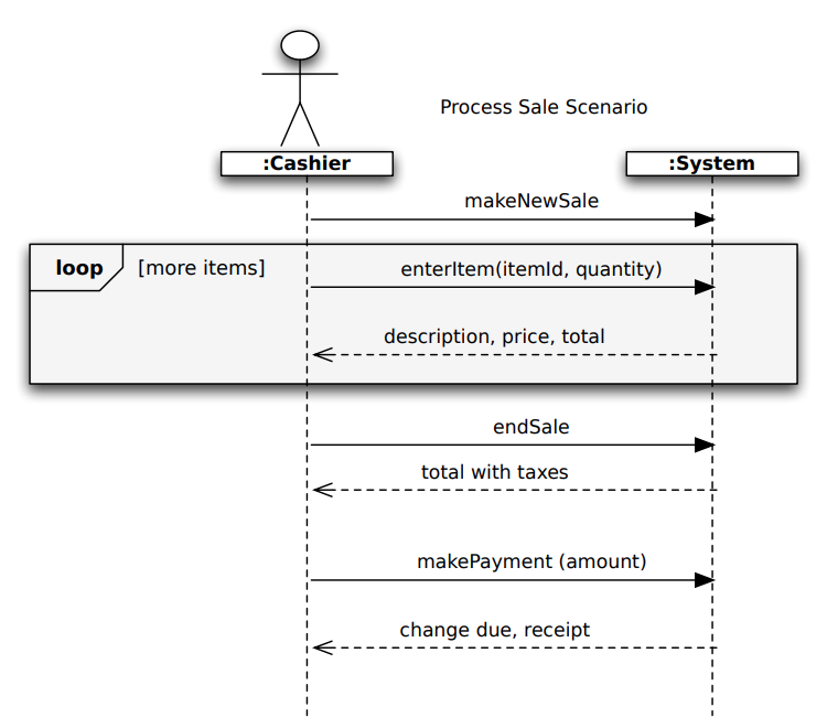
Source: github
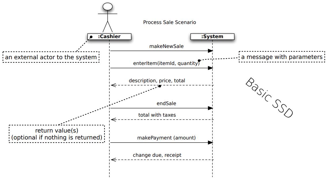
In the above illustration, the cashier that is an actor starts the new sale. Then the actor enters the item identifier, and then the system monitors the sale line item and presents item description, price, and running total.
The system produces the total with all the taxes calculated. Then the information is told to the customer, and the payment is received, and in last, the system is handling the payment.
The system sequence diagram depicts the control flow of use cases and the events related to them. You can track the logic of procedures, functions, or operations with the system sequence diagram. It makes you understand how the control is flowing by the interaction of the actor and a system. It helps you in making any transition in your design.
It is very inefficient to make the System Sequence Diagram by the hands because it is vulnerable to many deadly mistakes. Plus, when your system becomes more complex as the objects and actors increase, it isn't elementary to do this task by hand.
As a professional or a student software developer, you can use computer software to make your UML diagrams. The well-known software is the EdrawMax, the best diagram-making software and provides you suggestions on any diagram you are making with the help of the software.
The software is straightforward to use as it implements the drag-and-drop methodology to make the diagrams. It also contains dozens of shapes, symbols, etc., in its libraries to represent your diagram accurately. The software is free for your primary work, but more advanced features are available in the premium version.