Guides for Electrical Drawing Reading
Do You Want to Draw an Eletrical Diagram with Ease? Try This On!
EdrawMax Eletrical Drawing Tool helps to create professional electrical drawings for free with easy-to-edit templates and symbols. Just try it now for free!
Part 1: How to Read A Electrical Drawing
1. Familiarize with Standardized Electrical Symbols
Knowing the meanings of basic electrical symbols in your electrical drawing will help you quickly understand and troubleshooting the circuit.
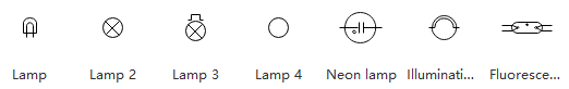
Lamp: Usually represented as a circle with a cross inside it. When the current passes through the lamp, it will produce light.
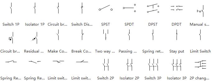
Switches: Symbolized by an opening or break in the line. It looks like the flip of a light switch.
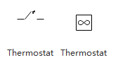
Thermostat: Is a kind of thermal switch that is triggered by the changes of temperature.
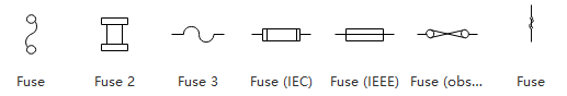
Fuse: Represented by a slight zigzag in the line. Motors are displayed by bumps along the line. It looks like an "M" with 5 or 6 humps.
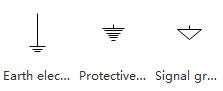
Ground: Represented by either a triangle pointing down or a set of parallel lines that become shorter as they appear below each other, in effect representing the inner area of the triangle pointing down. Ground is a common reference point that schematics use to show the overall unity of the various functions of the circuit. It does not refer to the actual ground of the earth.
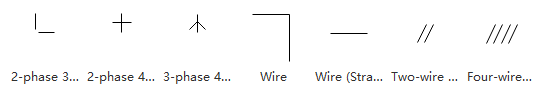
Wires: Used to link the devices together. All points along the wire are identical and connected. Wires may cross each other on an electrical drawing, but that does not necessarily mean that they connect. If they do not connect, one will be shown looping around the other in a semicircle. If they do connect, they will cross, and a dot will be seen at the point where the lines cross.
Use These Symbols to Design an Electrical Diagram! Try Now!
EdrawMax Electrical Drawing Software gives different options for choosing. You can use pre-made templates to create wiring draws, circuit draws, electrical engineering draws, layout draws, house wiring plan, etc... Try Free!
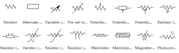
Resistors: Act to impede the flow of the circuit to an extent determined by the resistance value used. They are used to scale and shape the signal.
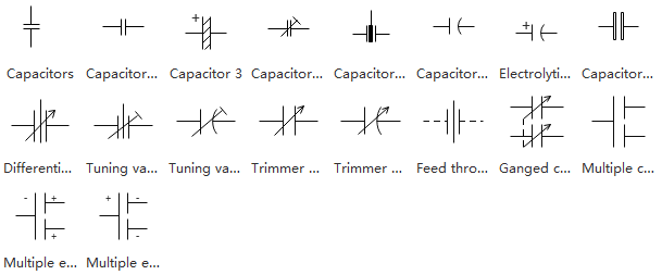
Capacitors: Used to control rapidly changing signals, as opposed to the static or slowly changing signals that are conditioned by resistors. The traditional use of capacitors in modern circuits is to draw noise, which is inherently a rapidly changing signal, away from the signal of interest and drain it away to the ground.
2. Learn Reading Pattern
Read schematics in the pattern that you would read the text. With rare exceptions, schematics should be read left to right and top to bottom. The signal generated or used by the circuit will flow in this direction. The user can follow the same path that the signal uses to understand what the signal does or how it is being modified.
3. Identify Polarity
Some components to a circuit board are polarized, meaning that one side is positive and the other negative. It means that you have to attach it in a specified way. For most symbols, polarity is included in the symbol. To identify the polarity of the physical part, a general rule of thumb is to find out which metal lead wire is longer. The longer part is the + side.
4. Understand Names and Values
Values help define what a component is. For electrical components like resistors, capacitors, and inductors, the value tells us how many ohms, farads, or henries they have. For other components, like integrated circuits, the value may be the name of the chip. Crystals might list their oscillating frequency as their value. The value of a schematic component calls out its most important characteristic.
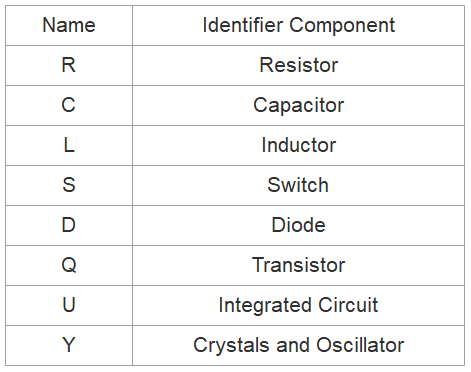
Common components and their name prefixes
Component names usually consist of one or two letters and a number. The letter part of the name represents the type of component - R's for resistors, C's for capacitors, U's for integrated circuits, etc. Each component name in an electrical drawing should be unique; if you have multiple resistors in a circuit, for example, they should be named R1, R2, R3, etc.
Components' names help us reference specific points in schematics. The prefixes of names are pretty well standardized. For some components, like resistors, the prefix is just the first letter of the component. Other name prefixes are not so literal; inductors, for example, are L's (because the current has already taken I [but it starts with a C...electronics is a silly place]). Above is a quick table of common components and their name prefixes.
EdrawMax
Handy Eletrical Drawing Tool >>
- Offers the latest signs and symbols to draw customized electrical diagrams.
- Allows creating a layout to illustrate the dimensions, directions, and notations.
- Create more than 280 types of diagrams effortlessly.
- Cross-platform supported (Windows, Mac, Linux, Web).
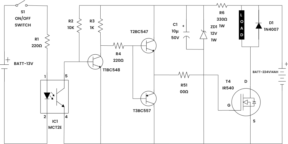
Part 2: Electrical Drawing Example
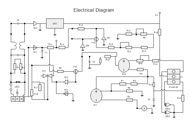
Using these above electrical symbols can help you draw standard electrical diagrams. Adding the components' names on each symbol makes it easier for both beginners and professionals to understand the circuits in seconds. Here are some good-looking electrical drawing examples, and you will find more in Edraw Template Center.
Or you can start from a video tutorial to learn how to draw an electrical diagrams with a useful tool!
Basic Electrical Diagram
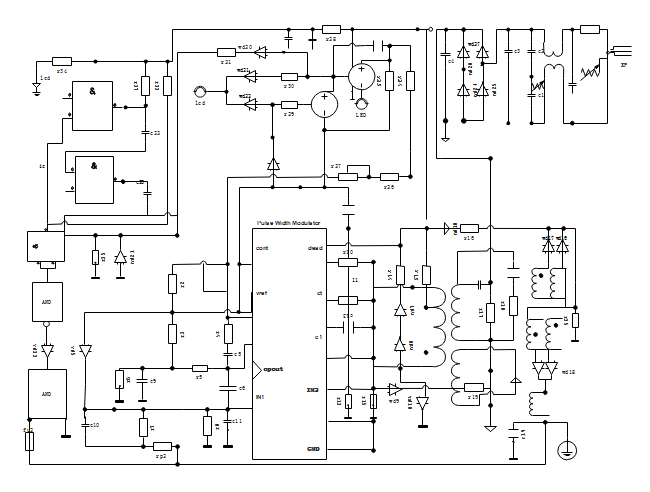
Electrical Wiring Diagram
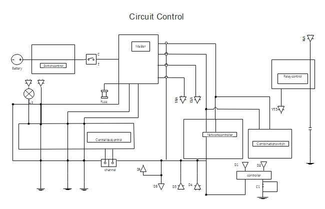
Circuit Control Diagram
More Related Articles
Integrated Circuit Schematics Software


