Process Flow Diagram
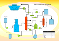
Process Flow Diagram (PFD) is a simplified sketch that uses symbols to identify instruments and vessels and to describe the primary flow path through a unit. It illustrates the general plant streams, major equipments and key control loops. They also provide detailed mass/energy balance data along with stream composition and physical properties.
Process Flow Diagram Software
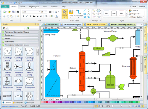
Edraw Max professional version includes more than 500 vector process flow diagram symbols and examples. It helps you more easily create process flow diagrams for piping systems, industrial, process, vacuum, fluids, hydraulics and air and gas drawing.
Free Download Process Flow Diagram Software and View All Examples

An all-in-one platform for 210+ diagrams.
・ Simple alternative to Visio
・ 26k+ symbols
・ 10K+ free templates
・ 10+ AI diagram generators


System Requirements
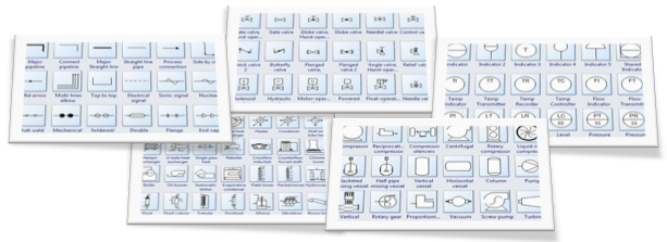
Process Flow Diagram Symbols
Process flow diagrams use special shapes to represent different types of
equipments, valves, instruments and piping flow. Edraw designs standard sets of
symbols used to depict mechanical equipment, piping, piping components,
valves, equipment drivers and instrumentation and controls. These pfd symbols
are assembled on the drawing in a manner that clearly defines the process flow.
How to Draw a Process Flow Diagram
The easiest way to draw process flow diagram is starting with a Edraw template.
By dragging process engineering equipment shapes onto your drawing page, connecting them with smart pipelines, and then dragging valves and instruments onto the pipelines, identifying equipment in your drawing, you can create intelligent tags.
You can make a process flow diagram more useful by adding information beside the equipment, pipelines, valves, and instruments. As you modify diagrams, you can easily generate new lists.
How to Create a Process Flow Diagram
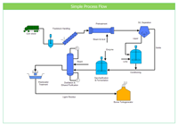
Examples of Process Flow Diagram
The following process flow diagram examples were drawn with the Edraw software. These diagrams are sometimes called piping flow diagrams.
|
|
|
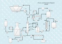
| Simple Process Flow | Process Flow Diagram | Process and Instrument Diagram |
The Benefits of Process Flow Diagram
The process flow chart providing a visual representation of industrial process equipment is interconnected by a system of pipelines. It has the following six benefits.
-
Gives everyone a clear understanding of the process.
-
Shows the plant design basis indicating feedstock, product and main streams flow rates and operating conditions.
-
Help to identify the scope of the process.
-
Facilitate teamwork and communication.
-
Shows graphically the arrangement of major equipment, process lines and main control loops.
-
Improves utilities which are used continuously in the process.
Other Process Flow Diagram Resource
Process and Instrumentation Diagram
Process Flowchart VS Use Case Diagram


