How to Create UML Component Diagram Effortlessly
Part 1: What is The UML Component Diagram?
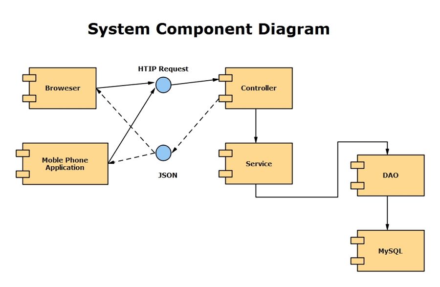
UML component diagram is a diagram describes how components are wired together to form larger components or software systems. It is often used to illustrate the pieces of software, embedded controllers and some other parts that make up a system and the structure of a it. The main purpose of UML component diagram is to show the structural relationships between the components of a system.
Unified Modelling Language (UML) is a type of language used to illustrate the inner workings of a system, which include its actors, actions, roles, and classes. Originally used in the fields of software and engineering, UML has now made its way into business, and is a popular method of documenting business processes.
The Usage of UML Cpmponent Diagram
UML component diagram is a special type of UML diagrams which is used to visualize the static implementation view of a system and describe the organization of the components in a system. Software designers and developer usually use it to model the components of a system, database schema, executables of an application and system’s source code.
- To model the hardware topology of a system.
- To model embedded system.
- To model hardware details for a client/server system and a distributed application.
- Forward and reverse engineering.
Part 2: How to Create A UML Component Diagram?
How to make a UML component diagram easily? Using EdrawMax to create your own UML component diagram in minutes. If you have had Edraw installed, you can create a more detailed UML component diagram by using the UML component diagram templates.
Step 1: Open EdrawMax desktop software or EdrawMax web-based application.
Step 2: Navigate to [New] > [Software] > [UML Modeling] in EdrawMax.
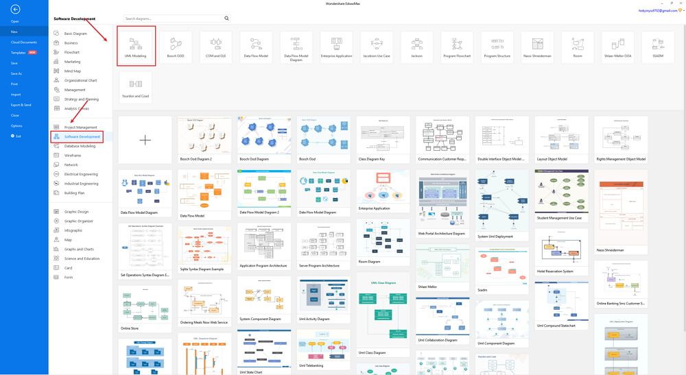
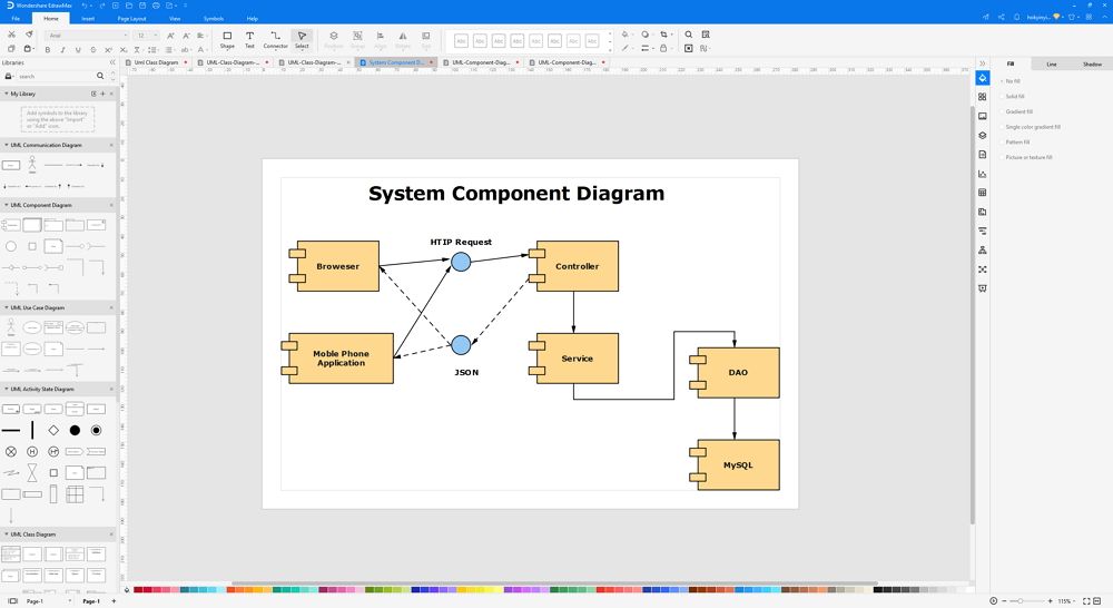
Step 3: Select one UML component diagram template to edit on it or click the [+] sign to start from scratch. Also, you can use massive UML component diagram symbols and elements from libraries in left menu to customize your UML component diagram.
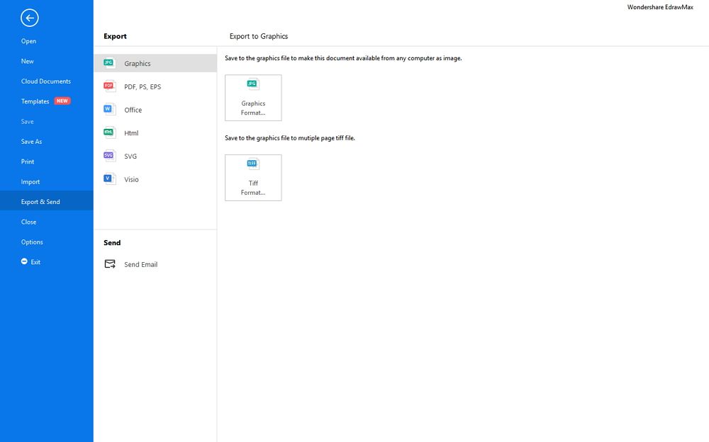
Step 4: Once finished your creation, you can export the file in multiple formats, including Graphics, PDF, editable MS Office file, SVG and Visio vsdx file.
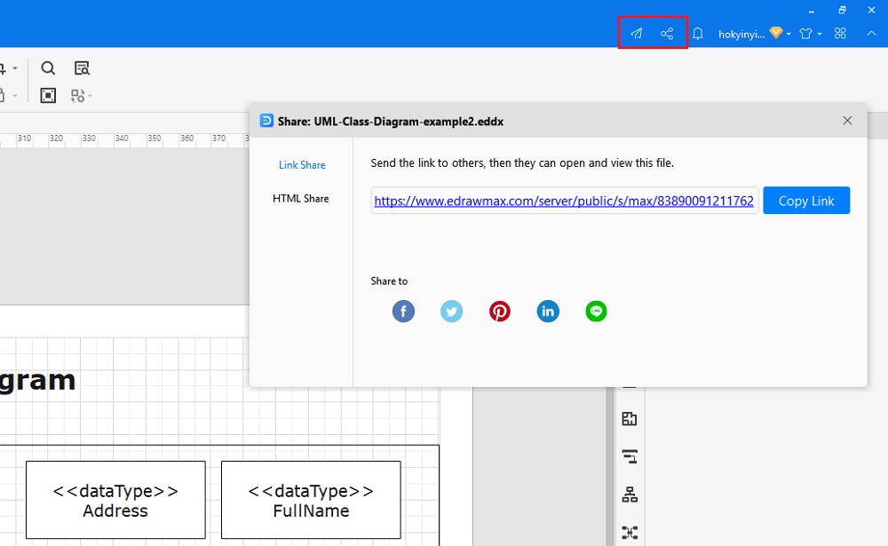
Step 5: Besides, you can share your UML component diagram with others via social media and web page. Or publish your UML component diagram in EdrawMax template gallery to show your work with others.
Part 3: UML Component Diagram Maker - EdrawMax
One of the most powerful programs that can compete with Microsoft Visio, EdrawMax is yet another diagramming software available for Windows, macOS, and Linux. The tool has several categories for almost all types of industries, and each category further has numerous templates to choose from, thus saving you a lot of time that you would otherwise waste in structuring a diagram, UML component diagram for this example, from scratch.
Price: free to use, lifetime plan for individuals, license for team and business.
Part 4: UML Component Diagram Examples
Following are a few UML component diagram examples that would help you understand the diagram versatility.
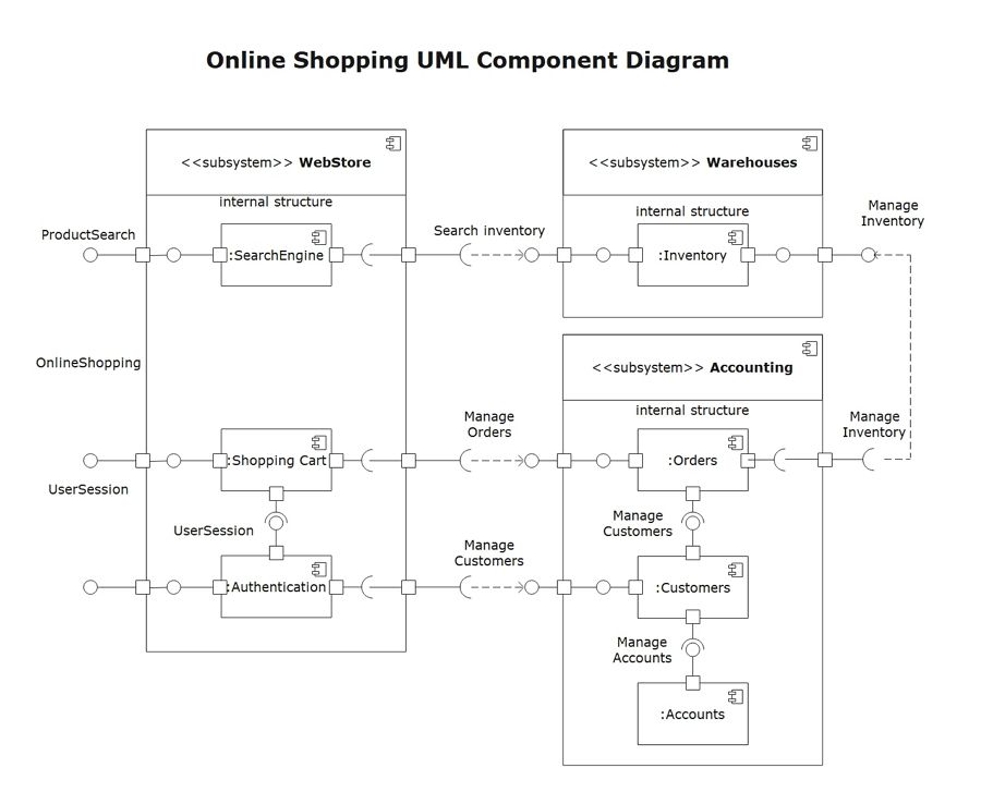
This UML component diagram illustrates the relationship between three subsystems for an online shopping platform. The three subsystems are WebStore, Warehouses, and Accounting. The WebStore’s components include Search Engine, Shopping Cart, and Authentication.
Searching for a product using the Search Engine function will require assistance from the Inventory component under Warehouses. The Shopping Cart component is linked to the Orders component under Accounting, and the Authentication component is linked to the Customers component under Accounting. The diagram illustrates how each subsystem is reliant on another for the entire system to function properly as a whole.
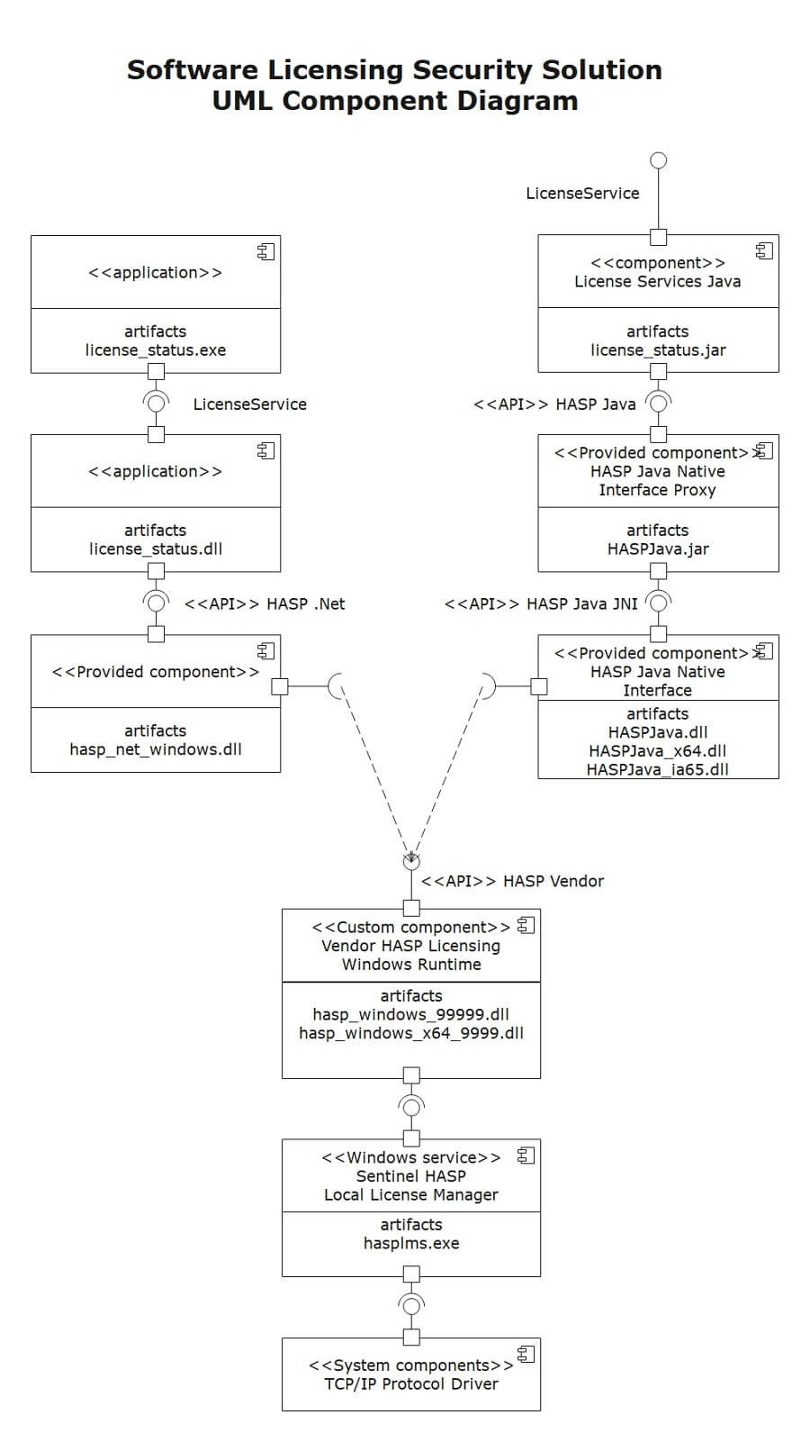
This UML component diagram depicts a system utilizing SafeNet Sentinel HASP Software Licensing Security Solution and Licensing API. Software implemented using Sentinel HASP - License Status.
Net application and LIcense Service Java component can be seen at the top of the diagram. In order to show that the license status has been implemented by license_status.exe artifact, the License Status application is used. The License Service interface is implemented by the License Services Java component.
Part 5: Conclusion
According to this article, there are mainly four parts to illustrate what is the UML component diagram, to tell you how to create a UML component diagram in EdrawMax, and to show you how easy and helpful EdrawMax tool is, then shows some UML component diagram examples. Creating a detailed UML component diagram with Edraw is an effective way to design and document a computer network, like the following illustration.
EdrawMax is an easiest all-in-one diagramming tool, you can create UML component diagrams and any other type diagrams with ease! With substantial UML component diagram symbols and cliparts, making UML component diagrams could be as simple as possible. Also, it supports to export your work in multiple formats and share your work with others. Get started to create your UML component diagram now!
