How to Create a P&ID Drawing
Part 1: What is P&ID?
Piping and instrumentation diagrams (P&ID) are used engineering - specifically in the process industry - to show piping components in a process flow. P&IDs will include important piping details (dimensions, flow direction, etc.), safety requirements, and mechanical equipment needed.
P&IDs are a form of schematics. They are most commonly used by engineers designing manufacturing processes for industrial plants. They are helpful as a layout and blueprint of a plant, for allowing engineers to evaluate construction processes, and acting as a guideline for standards of safe facility operation.
Part 2: What is a P&ID Used For?
- It shows the inner relationship of how each instrument is connected.
- It shows the relative location of equipment, actuators, and instruments in a process.
- It depicts a conceptual outline of a plant and its control architecture.
- It provides a common language for documenting, discussing, and analyzing a plant.
Part 3: How to Make a P&ID Effortlessly?
Step 1: Start EdrawMax.
Step 2: Navigate to [New]>[Industrial Engineering]
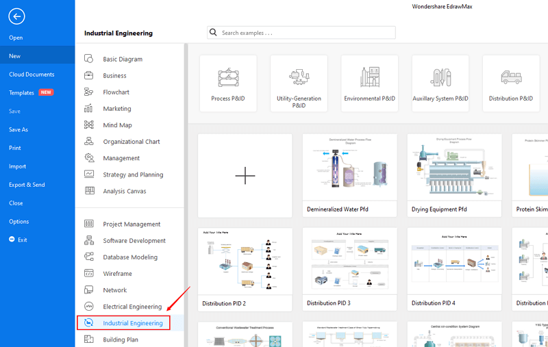
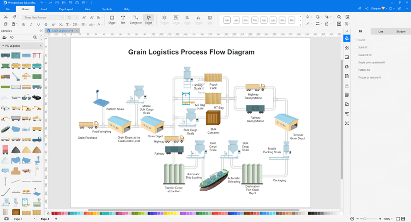
Step 3: Select one P&ID template to edit on it or click the [+] sign to start from scratch.
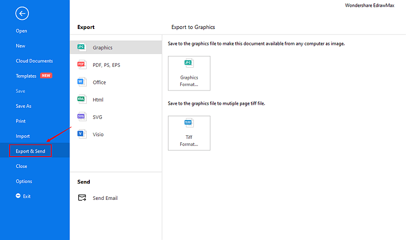
Step 4: You can export the file to Graphics, PDF, editable MS Office file, SVG and Visio vsdx file.
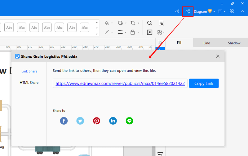
Step 5: And you can share your diagram with others via social media and online website page.
Part 4: Built-in P&ID Symbols in EdrawMax
One of the features that makes Edraw an outstanding P&ID designer is its vast collection of symbols. This following picture shows only the tip of iceberg.
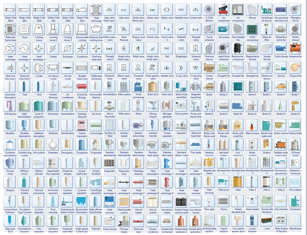
Symbol Categories:
Part 5: P&ID Examples
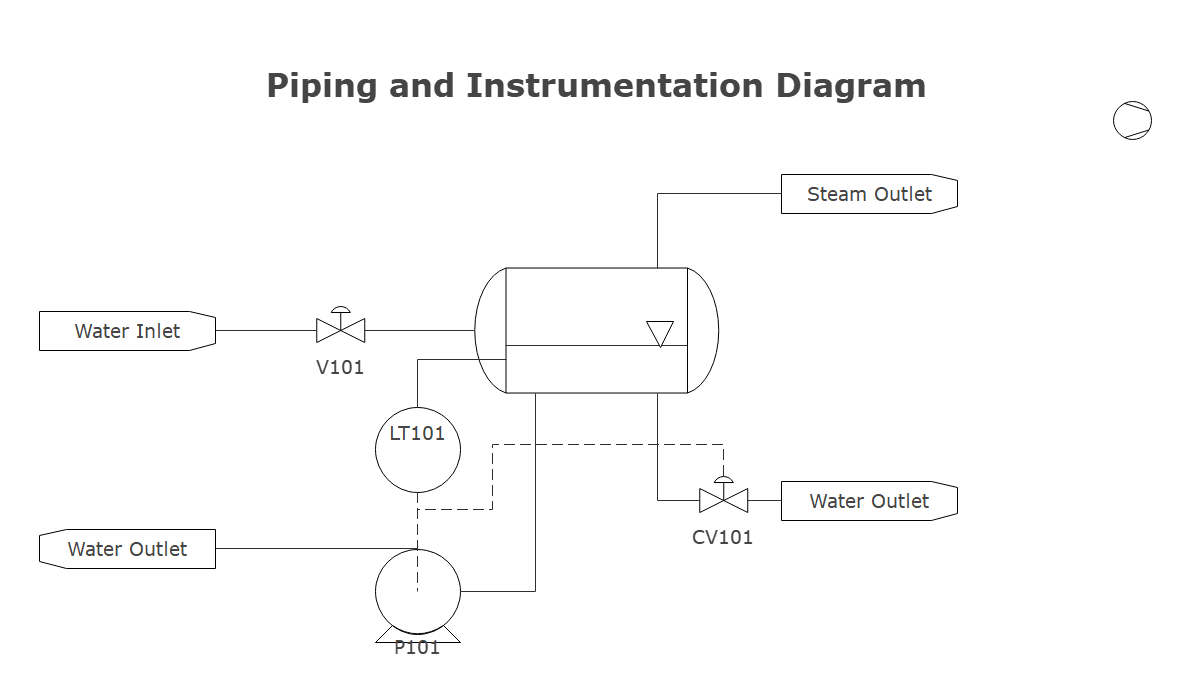
Example 1: Piping and Instrumentation Diagram
This piping and instrumentation diagram illustrates how a flusher level control system functions. P&IDs will often include important piping details (dimensions, flow direction, etc.), safety requirements, and mechanical equipment needed.
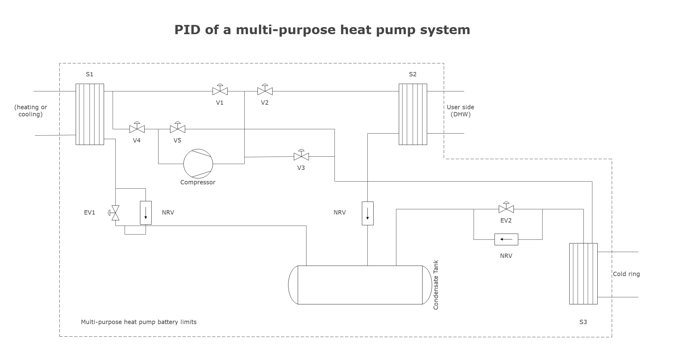
Example 2: PID of a Multi-purpose Heat Pump System
This piping and instrumentation diagram illustrates how a heat pump system functions. It includes components such as heat exchangers (S1, S2, S3), solenoid valves (V1, V2, V3, V4, V5), expansion valves (EV1, EV2), and non-return valves (NRV).
Part 6: Conclusion
According to this article, there are mainly five parts to illustrate what is P&ID, to tell you what a P&ID is used for, to tell you how to create a P&ID, to introduce some built-in P&ID symbols in EdrawMax to you, and to show you some P&ID examples.
EdrawMax is an easiest all-in-one diagramming tool, you can create P&IDs and any other type diagrams with ease! With ready-made P&ID symbols and cliparts, making P&IDs could be as simple as possible. Also, it supports to export your work in multiple formats and share your work with others. Get started to create your P&IDs now!

An all-in-one platform for 210+ diagrams.
・ Simple alternative to Visio
・ 26k+ symbols
・ 10K+ free templates
・ 10+ AI diagram generators


