Process and Instrumentation Drawing Software

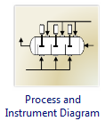
Process and Instrumentation Diagram
The Process and Instrumentation Drawing or P&ID is also known as the mechanical flow diagram and piping and instrumentation diagram. A P&ID is a complex representation of the various units found in a plant. It is used by people in a variety of crafts. The primary users of the diagrams after plant startups are process technicians and engineering personnel.
The Process and Instrument diagrams can provide the information needed by engineers to begin planning for the construction of the plant. A P&ID can show how the industrial process equipment is interconnected by a system of pipelines. P&ID schematics also display the instruments and valves that monitor and control the flow of materials through the pipes.
Process and Instrumentation Drawing Software
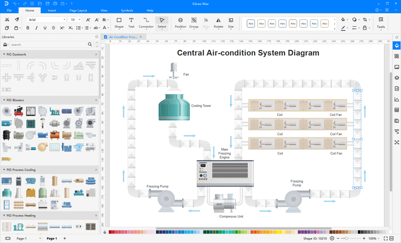
EdrawMax allows you to easily create piping and instrumentation diagrams with pre-designed examples and symbols. There are a variety of drawing tools and smart connectors. You can simply drag and drop P&ID shapes into the canvas to complete your drawings.
In addition, Edraw process and instrumentation drawing software is compatiable with all platforms, which can run on Windows, Mac OS, Linux and Web.

An all-in-one platform for 210+ diagrams.
・ Simple alternative to Visio
・ 26k+ symbols
・ 10K+ free templates
・ 10+ AI diagram generators


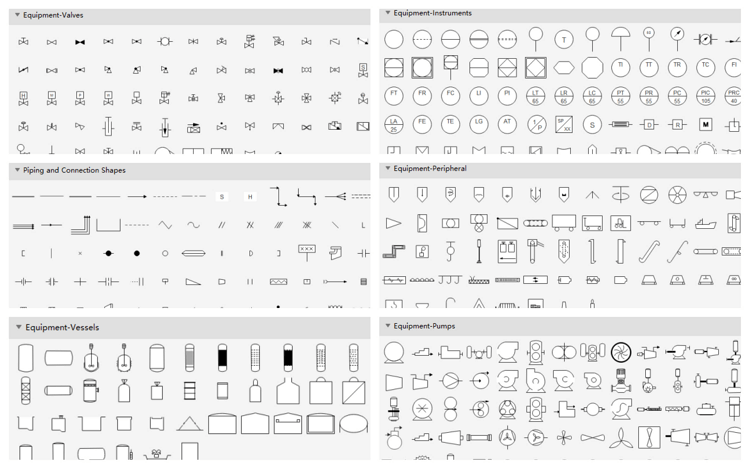
Process and Instrumentation Drawing Symbols
Process technicians use special P&IDs to identify all of the equipment, instruments, and piping found in their units. Edraw includes more than 500 standard P&ID symbols used to depict industrial, process, vacuum, fluids, hydraulics, and air and gas. These P&ID symbols represent mechanical equipment, piping, piping components, valves, equipment drivers, instrumentations, and controls.
How to Draw a Process and Instrumentation Diagram
The easiest way to draw process and instrumentation diagrams is starting with a pre-made template by Edraw.
Drag P&ID symbols onto your drawing page, connect them with smart pipelines, and then drag valves and instruments onto the pipelines.
You can make a process and instrumentation diagram more useful by adding information beside the equipment, pipelines, valves, and instruments. As you modify diagrams, you can easily generate new lists.
Besides, you can look at the video below and know how to make a P&ID with professional software in minutes!
How to Create a Process and Instrumentation Diagram
Examples of Process and Instrumentation Diagram
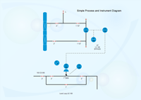
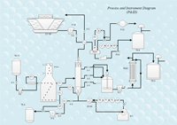
The following process and instrumentation drawing examples are drawn with the Edraw software. These simple examples elaborate on how a system of pipelines interconnects industrial process equipment. P&ID schematics examples also show the instruments and valves that monitor and control the flow of materials through the pipelines.
|
|
|
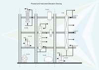
| Pfd Elevation Drawing | Simple P&ID Diagram | Process and Instrumentation Diagram |
The Advantages of Process and Instrumentation Diagram
The process and instrument diagram provides a visual representation of industrial process equipment interconnected by a system of pipelines. It has the following six advantages.
- Gives everyone a clear understanding of the instrument process.
- Represents the sequence of all relevant operations occurring during a process and includes information considered desirable for analysis.
- Helps to identify the scope of the process.
- Presents events that occur to the materials.
- Incorporates specifications, standards and details that go into the design.
- Facilitates teamwork and communication.
- Shows graphically the arrangement of major equipment, process lines and main control loops.
- Improves utilities which are used continuously in the process
- Digs into all the gory details about materials of construction
Read More
A Handy Guide to Process Flow Diagram


