Electrical Symbols
Part 1: What Are The Electrical Symbols
Electrical symbols are the standard technique to represent an electrical circuit. It makes the graphical representation easier to work on and implement. The electrical symbols represent various components, devices, and functionalities present in a circuit. It helps to show the details of an electrical diagram so that the engineer can adequately plan a circuit before actually working on it.
If you are willing to design a electrical diagram but don't know how to start, EdrawMax can help you much.
EdrawMax
Powerful Electrical Diagram Maker >>
- Superior file compatibility: Import and export drawings to various file formats, such as Visio
- Cross-platform supported (Windows, Mac, Linux, Web)
Part 2: Types of Electrical Symbols
There are a variety of electrical symbols, including Common electronic symbols, historical electronic symbols. The users can also follow the different standards including, the IEEE standard, IEC (International Electrotechnical Commission), Std., ANSI, JIC, Australian Standard, and more.
Basic Electrical Symbols

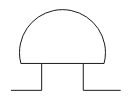
A ground symbol or a ground terminal works as electrical shock protection. It is a zero potential reference point from where an electrician measures the current.

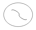
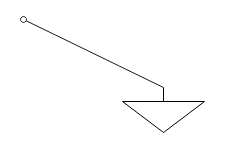
The antenna is mainly a device or rods that can capture different waves and signals, including electromagnetic waves, electric signals, and more.

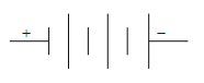
A battery symbol has two disjointed and disproportionate parallel lines. The lines are present to signify the series cells in the battery.

The source is a power source for an electronic device when there are plus and minus signs that indicate a DC when it has a wave that signifies AC.
The Fuse protects a circuit from getting burnt by disconnecting it when the current flow through the circuit goes beyond the set limit. The Fuse has a wire which gets melt while the connection gets disconnected.

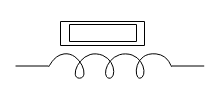
An inductor or reactor is like a coil present in a magnetic field or flux to conserve energy.
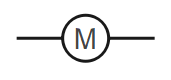
A motor is an electronic device that works on transforming electric energy into a mechanical one.
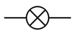
Bulb
A bulb as an electric symbol looks like a circle that has a cross in the middle, and it gives an output by getting light up when a current passes through it.

Transformers are present in an AC circuit after being coupled by a magnetic flux. They reduce the tension in a circuit by maintaining the frequency.

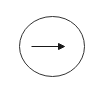
A coaxial plug in an electrical circuit works as a transmission line. It delivers radio frequency signals and cable television signals. Coaxial plugs in an electrical symbol diagram look like a circle on top of an arrow and another arrow passing through it.

Switches are of a diverse variety, for example, single-pole single-throw, pushbutton, dip, relay, and more. A switch connects a circuit when it is closed and disconnects the circuit when open.

Resistors in an electrical diagram look like wavy lines with pointed ends. The resistors control the current flow in a circuit by dividing voltage, terminating transmission lines, and more.
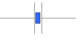
Capacitor
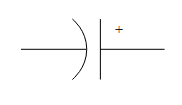
A capacitor symbol has two terminals with two plates. There is a curved surface having a lower voltage, which identifies a capacitor as polarized.
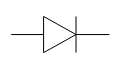
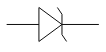
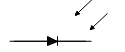
Diode
A diode is a device that allows the current flow to a single direction after being polarized with an anode and a cathode side.
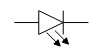
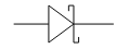
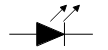
Diode LED
The Diode LED looks similar to a usual diode symbol with small arrows that indicate the radiation of light.
Use All Kinds of Electrical Symbols to Draw Schematic Diagrams!
You need EdrawMax Electrical Diagram Maker to design a circuit. All can be done within a minute with various electrical symbols and templates! Give it a shot!
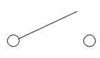
Wires
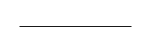
A straight line represents the electrical wire or a power line in an electrical diagram, and it works as the conductor of electric current in the circuit diagram.
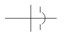
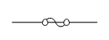
Not Connected Wire
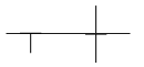
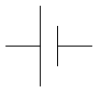
The Not connected wire shows when in a circuit, there are two unconnected wires. A designer can draw two parallel lines with a half-circle on one line at the middle parts where it bisects the third line to represent not connected wires.
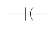
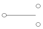
Connected Wire
Connected wire in a circuit allows the current to travel from one point to another. The connected wire symbol looks like two parallel lines emerging from a two-point while one gets extended. Connected wire represents the connection between two conductors.
Switches

A Single Pole Single Throw switch is an ON/ OFF switch with the poles to stand for the number of poles to connect.

SPDT Toggle Switch
A Single Pole Double Throw Switch lets the current flow in a circuit adjust its position to two directions

The Pushbutton Switch that is usually open needs a switch to turn ON. The user needs to push the button to switch it on. Otherwise, it is open.

Pushbutton Switch (N.C.)
The Pushbutton Switch usually is closed, which means they usually are in the ON stage, and the user needs to release it to turn it OFF.
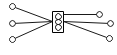
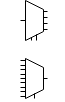
DIP Switch
The DIP Switch allows the user to select one from 0 to 5 volts. They are not grounded and therefore require external sources.
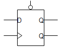
SPST Relay
SPST relay has four terminals, two terminals for staying connected or disconnected, while two others are for two coils.

Jumper
The jumper switch, a small metal connector, works as an ON/OFF Switch, and they are widely used together for the configuration of hardware devices.

Solder Bridge
The Solder Bridges serve as permanent switches. When a user solders between the two parts of the bridge, it gets shorted while disconnecting it. They need to desolder it.
SPDT Relay
SPDT Relay is a way to switch between two circuits and has a coil, a common terminal, a closed terminal, and a normally open terminal if the coil remains closed, the common terminal and the normally closed terminal works.
Download EdrawMax Electrical Diagram Maker
Sources/Power Supply symbols
The symbol represents AC supply or alternating current supply in a circuit. The current flow continuously changes direction.

DC supply is a supplier of electric energy in a circuit, and the Direct Current has current flow in a single direction.
A constant source is an independent current source that is responsible for a constant current flow.

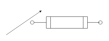
A controlled current source works while depending on the current input. It is present in an electric circuit to either deliver or absorb current. The symbol has a circle and an arrow sign that shows the current flow.
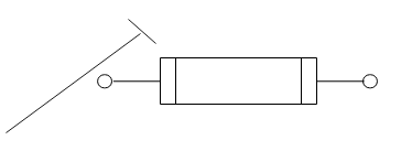
A controlled voltage source in a circuit looks like a diamond-shaped quadrilateral with a positive sign and a negative sign. The voltage in the circuit controls the controlled voltage sources.
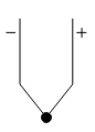
A single-cell battery in a circuit looks like two unmatched parallel lines, one big and one small, representing one cell.
Multicell battery has multiple small and big lines, which represent multiple cells identifying as cathode and anodes.

A generator in a circuit acts either as a voltage source or a current source. Moreover, a generator can also fit into a circuit based on this.
Ground
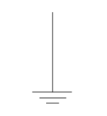
Earth ground is a zero potential ground that has a potential to conduct to earth.
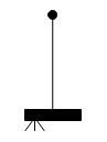
Chassis ground protects a user from electric shock by creating a barrier between the user and the circuit.
It is an arbitrary reference point that is relative to the potential of the earth's ground.
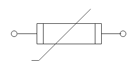
Resistor and Varible Resistor
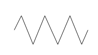
It is a symbol of a fixed resistor and looks like waves with pointed heads and gets connected to two points at the end.
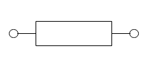
The resistor is a two-terminal device, and the IEC standard resistor symbol looks like a bar connected to two points.
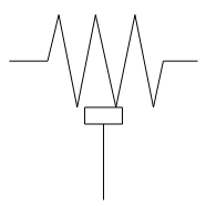
It is a three-terminal resistor that creates an adjustable voltage in an electrical circuit.
It is a three-terminal resistor that creates an adjustable voltage in an electrical circuit.
Tapped resistor uses one or more terminals in the devices, which are voltage-dividers.
An Attenuator is a circuit dissipating the current flow to step down the voltage.
A memristor is a semiconductor that works as a joining point for capacitors, inductors, and resistors.
The device helps to create a variable current by creating a variable resistance.
A preset is a component that offers variable resistance to an electrical circuit.
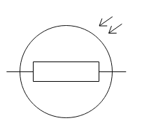
Magneto resistor shows a change in resistance when an external magnetic field affects it.
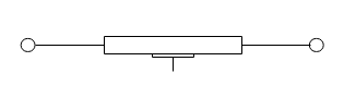
The IEC symbol of a variable resistance has a bar, similar to the symbol of a resistor. However, to show the variable current, there is an arrow.
A trimmer resistor or a trim pot adjusts a circuit and helps calibrate a new device.
It is a resistance thermometer dependent on the temperature.
It is a device that helps to create resistance by converting light energy or brightness.
Use All Kinds of Electrical Symbols to Draw Circuit Diagrams!
You need EdrawMax Electrical Diagram Maker to design a circuit. All can be done within a minute with various electrical symbols and templates! Give it a shot!
Capacitor
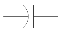
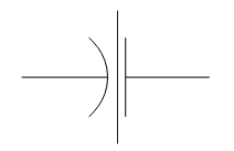
A capacitor is an electrical circuit that looks like a straight line and a half-circle line posed side by side.
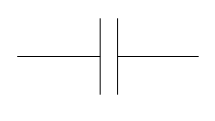
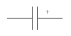
To express an unpolarised capacitor in a circuit, the user can use parallel marks with lines going on sides.
The polarized Capacitor shows a straight plate and a curved one. The straight plate stands for an anode, while the curved plate is a cathode.
Two separate straight lines represent a polarized capacitor while one of them is a cathode and another plate or line signifies an anode.
It is a capacitor that can have its capacity changed mechanically or electronically.
A feedthrough capacitor has a dielectric layer and helps in carrying signals through an enclosed path.
Inductors
The Inductor is an electronic device that stores electronic energy as magnetic energy.
Iron core inductors have high inductance, and a coil and a rod represent it.
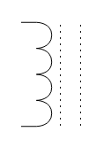
Two dotted lines with a coil help represent a ferrite core inductor, and it is information one must know.
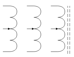
Center tapped Inductor is an element in a circuit that helps in coupling signals.
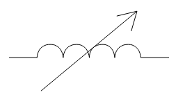
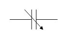
Variable inductors with varied inductance look like an inductor with an arrow to represent its variable nature.
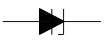
Diode
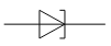
This device directs current flow in a single direction.
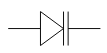
Zener diode is one of the devices that helps to maintain a fixed voltage
It is a semiconductor with a less forward voltage drop.
Varicap diodes show a wide range of capacitance, and it depends on the voltage.
It is a semiconductor that creates a negative resistance with the process of tunneling.
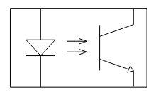
It is a semiconductor that gets light up when current passes through it.
The Photodiode is a light-sensitive diode.

This four-layer semiconductor has a PNPN structure.

It is a solid-state semiconductor that works as a bistable switch.
A constant current diode is current-limiting or current-regulating in nature.

The laser diode is a semiconductor that converts electrical energy into light.
Download EdrawMax Electrical Diagram Maker
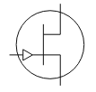
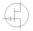
Transistor
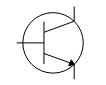
An NPN bipolar transistor passes electronics from the emitter point to the collector point.

It is a transistor that controls the electron flow from the emitter to the collector.

It is a device that has a compound structure with two bipolar transistors.
The JEFT-N transistors use electrons as a carrier of charge in a circuit.
The primary formation of its is there with P-type with two small parts of n-type.
The NMOS transistors work by creating an inversion layer of n-type in the p-type body of the transistor.
The PMOS transistors work by creating an inversion layer of the p-type in the transistor's n-type body.
Logic Gates
A Not Gate can use only one input and the output in a reverse of the user input.
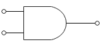
The AND Gate can work on two or more inputs, and the outputs can be accurate if the inputs are actual.
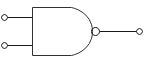
It can use two or more inputs, delivering accurate outputs unless all the inputs are valid.
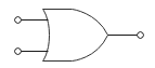
"OR Gate" also gets two or more inputs. To have an actual output in OR Gate, at least one of the inputs needs to be true.
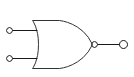
It is a logic gate with two or more inputs, and none of the input should be confirmed to get the accurate output.
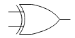
It uses two or more inputs, and when they are different, they can generate valid output.
A D-Flip-Flop logic gate takes two inputs and two outputs. The two inputs are clock inputs and data input.
It is a logic gate that channels several inputs into standard single output.

It takes one input to develop several digital outputs.

It is a logic inverter that allows it to produce either an actual or inverted output.
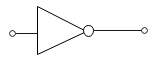
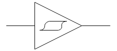
Amplifier

A primary amplifier symbol is a triangle symbol with one input and one output.
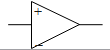
An operational amplifier amplifies weak electric signals, which have two input pins to give a single output pin.
Use All Kinds of Electrical Symbols to Draw Circuit Diagrams!
You need EdrawMax Electrical Diagram Maker to design a circuit. All can be done within a minute with various electrical symbols and templates! Give it a shot!
Antenna
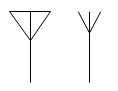
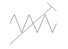
It is a generic symbol of an aerial antenna that uses three open ends at the top.

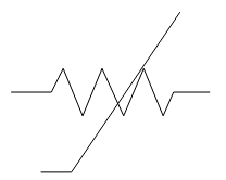
It uses two conductors of equal lengths and hence looks like two parallel lines.

It has a loop and works on a regular source.
Transformers
To increase or decrease AC voltage, the electricians use transformers. Two coils have wire linked to it.

It is a transformer that has a single iron core with two coils wound around it.

They get used on inductors for the coupling of signals.
Miscellaneous
It is a device that converts electrical energy to kinetic energy.

Transformers look like coils that use a core material.
It is also a device to convert electrical energy to sound.
It is a device to convert electrical energy to sound energy.
It is a safety device that melts when there is excessive current flow.
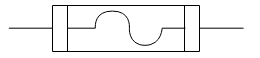
Fuse in a circuit prevents the short circuit by disrupting the current flow.

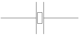
Bus in a circuit denotes the power flow.

The Bus in a circuit works for data or signals.
The symbol of the Bus may look like a both-sided line with a hollow space within.
This device used light to transfer signals between two separate circuits.
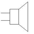
A Loudspeaker is a device that converts electrical energy to sound.
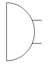
It is a device that converts sound energy into electrical energy.
It amplifies weak signals.
It is present in a circuit to convert an analog input to a digital output.
It changes an analog input to a digital one.
It works to convert the digital signal into an analog one.
It uses mechanical resonance to create an electric signal.
It uses frequency to form oscillations.

It is a symbol that signifies a single way flow of current.
Light bulbs show light when current passes through them.
It is a sensor for determining the temperature change.
Download EdrawMax Electrical Diagram Maker
Part 3: How to Use Electrical Symbols
It is easy for you to create an electrical diagram when you know where to find thousands of electrical symbols. You can watch the video below and learn how to create an electrical circuit diagram. Alternatively, you can follow the instructions of words and pictures step by step.
Wiring and Circuit Diagrams Maker- EdrawMax
The electrical symbols make it easier for the engineers to create an electrical diagram for their work. Though multiple devices make it seem not very easy, the user can work with the online tool, EdrawMax Electrical Diagram Maker, which can offer the user a user-friendly experience. The tool has a library with a wide range of electrical symbols that they can use. There are ready-made templates for inexperienced users to work on, making their work a bit effortless. When the work gets finished, it is easily to export the file in various formats and share it easily with others.
Step 1: Launch EdrawMax on your computer. An extensive collection of electrical diagram templates can be found in the Electrical Engineering category. Click the icon of Basic Electrical to open the library that includes all symbols for making electrical diagrams.
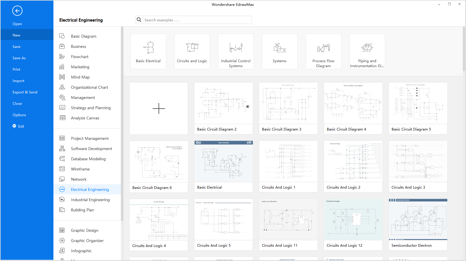
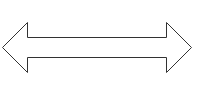
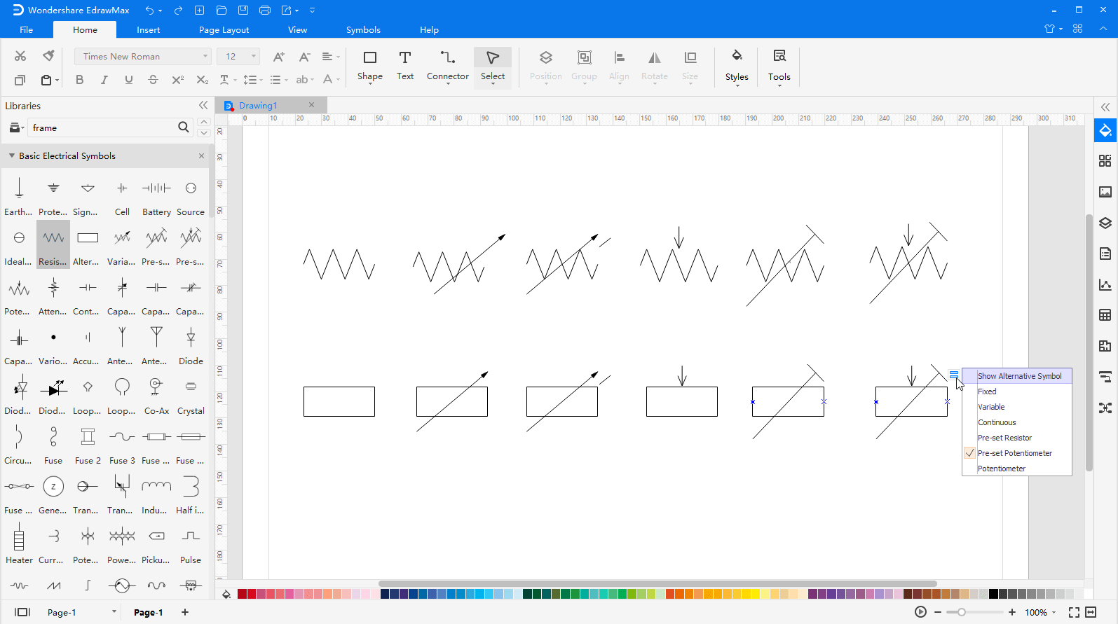
Step 2.1: As you are into the workspace of EdrawMax, drag the symbol that you need directly onto the canvas. You can resize the selected symbol by dragging the selection handles. A double-sided arrow shows the direction to which you can move the mouse, and you can only move the symbol when a four-direction arrow appears.
Step 2.2: You can also change the shape of the symbol via the floating menu/action button. It shows when the symbol is selected or when the pointer is over the symbol. For example, the resistor can have 12 kinds of variations.
Step 3: When your electrical diagram is complete, you can export it to JPG, PNG, SVG, PDF, Microsoft Word, Excel, PowerPoint, Visio, HTML with just a single click. So you can share your drawings with people who don't use EdrawMax with no need to looking for ways of converting file formats.

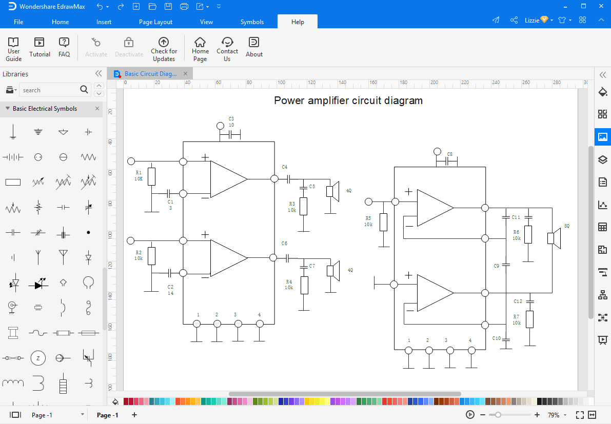
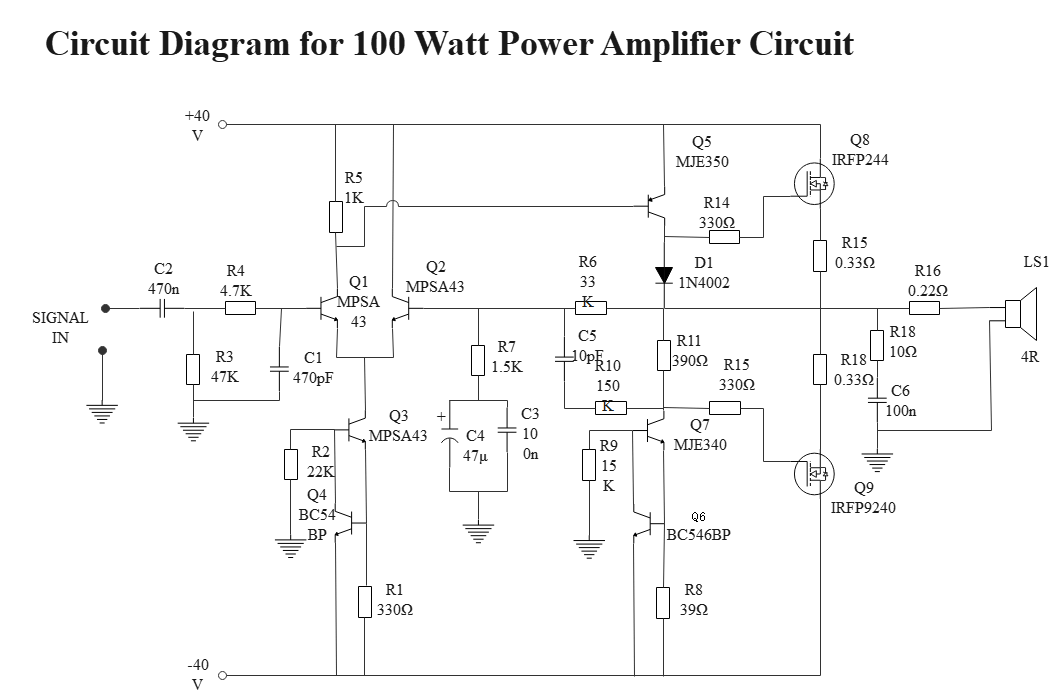
Wiring and Circuit diagram example
Here is an example of a circuit diagram for a 100-watt power amplifier. There is a signal which passes through several capacitors and amplifiers, and as the signal passes through them, it gets amplified. The output device in the circuit is a loudspeaker.
Part 4: More Electrical Symbols


