Electrical Engineering Diagram
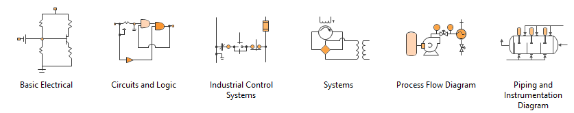
Create engineering diagrams such as electrical diagrams, circuit and logic diagrams, industrial control systems, process flow, P&ID and systems diagrams.
How to Create an Electrical Engineering Diagram
Open an Electrical Engineering Diagram Maker
On the File menu, point to New, select Engineering, and then click one of the followings:
- Basic Electrical
- Circuits and Logic
- Industrial Control Systems
- Systems
- Process Flow Diagram
- Process and Instrumentation Diagram
These templates open in an unscaled drawing page and you can change the settings at any time.

An all-in-one platform for 210+ diagrams.
・ Simple alternative to Visio
・ 26k+ symbols
・ 10K+ free templates
・ 10+ AI diagram generators


Choose from Industry-standard Eletrical Diagram Symbols
Drag any of the electrical component shapes onto the drawing page, select a shape, and then on the context menu, click Property. In the Shape Property dialog box, click on each item and type or select a value.
Connect Electrical Components Using Connector Tools or Connector Shapes
1. Use Connector Tools
Click the Connector tool.
Drag from a connection point on the first shape to a connection point on the second shape. The connector endpoints turn red when the shapes are connected.
![]()
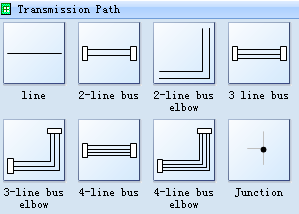
2. Use connector shapes
Drag a connector shape from the shape library onto the drawing page.
Place the connector's begin point on the parent shape (the shape you are connecting from).
Place the connector's end point on the child shape (the shape you are connecting to).
When the connector is glued to the shapes, the endpoints turn red.
Add Text to the Selected Shape
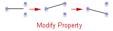
Label individual electrical component shapes by selecting the shape and typing.
Modify the Property of Symbols
Select SPST switch, then click the Set switch position item in the context menu.
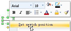
In the Shape Data dialog, choose a switch position.
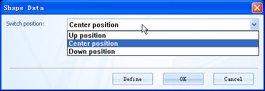
So you can change the switch position by the predefined shape data.
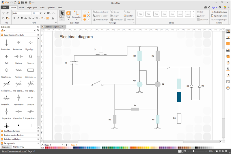
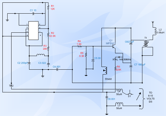
Electrical Engineering Diagram Examples
The following electrical engineering diagram is created by Edraw engineering diagram software. You can drag built-in electrical symbols then connect them easily.
More Related Articles


