Database Model Diagram
Draw database model diagrams effortlessly with Edraw!
Database Model Diagram Software is a very easy-to-use and intuitive database design tool and database model Diagram tool which can save you hundreds hours of work. It's a quick database model diagram software which helps you describe processes, interfaces, data stores, and data flows.
Edraw is an excellent tool for database model Diagram. It allows you to create database model diagrams and structures then export to detailed HTML or PDF reports.
Free Download Database Model Diagram Software
The Entity-Relationship Model
The Entity-Relationship (ER) model was originally proposed by Peter in 1976 [Chen76] as a way to unify the network and relational database views. Simply stated the ER model is a conceptual data model that views the real world as entities and relationships. A basic component of the model is the Entity-Relationship diagram which is used to visually represents data objects. Since Chen wrote his paper the model has been extended and today it is commonly used for database design For the database designer. The utility of the ER model is:
- it maps well to the relational model. The constructs used in the ER model can easily be transformed into relational tables.
- it is simple and easy to understand with a minimum of training. Therefore, the model can be used by the database designer to communicate the design to the end user.
- In addition, the model can be used as a design plan by the database developer to implement a data model in a specific database management software.
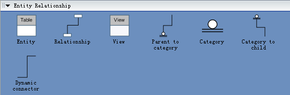
Symbols for Database Model Diagrams
With an extensive set of library objects such as entities, links, items, attributes, users, types, captions, inheritance, references, boundaries, events, clouds etc., Edraw is a perfect tool for database model design and ER diagramming.
The Database Model Diagram template helps you design and implement database structures. You can use both Entity-Relationship (ER) and Integrated Definition for Data Modeling (IDEF1X) notation when creating the diagram.
Entity Relationship Symbols
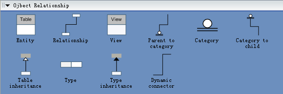
Object Relationship Symbols
Basic Constructs of E-R Modeling
The ER model views the real world as a construct of entities and association between entities.
Entities
Entities are the principal data object about which information is to be collected. Entities are usually recognizable concepts, either concrete or abstract, such as person, places, things, or events which have relevance to the database. Some specific examples of entities are EMPLOYEES, PROJECTS, INVOICES. An entity is analogous to a table in the relational model.
Entities are classified as independent or dependent (in some methodologies, the terms used are strong and weak, respectively). An independent entity is one that does not rely on another for identification. A dependent entity is one that relies on another for identification.
An entity occurrence (also called an instance) is an
individual occurrence of an entity. An occurrence is analogous to a row in the
relational table.
Special Entity Types
Associative entities (also known as intersection entities) are entities used to associate two or more entities in order to reconcile a many-to-many relationship.
Subtypes entities are used in generalization hierarchies to represent a subset of instances of their parent entity, called the supertype, but which have attributes or relationships that apply only to the subset.
Associative entities and generalization hierarchies are
discussed in more detail below.
Relationships
A Relationship represents an association between two or more entities. An example of a relationship would be:
- employees are assigned to projects
- projects have subtasks
- departments manage one or more projects
Relationships are classified in terms of degree,
connectivity, cardinality, and existence. These concepts will be discussed
below.
Attributes
Attributes describe the entity of which they are associated. A particular instance of an attribute is a value. For example, "Jane R. Hathaway" is one value of the attribute Name. The domain of an attribute is the collection of all possible values an attribute can have. The domain of Name is a character string.
Attributes can be classified as identifiers or descriptors. Identifiers, more commonly called keys, uniquely identify an instance of an entity. A descriptor describes a non-unique characteristic of an entity instance.
Classifying Relationships
Relationships are classified by their degree, connectivity, cardinality, direction, type, and existence. Not all modeling methodologies use all these classifications.
Degree of a Relationship
The degree of a relationship is the number of entities associated with the relationship. The n-ary relationship is the general form for degree n. Special cases are the binary, and ternary ,where the degree is 2, and 3, respectively.
Binary relationships, the association between two entities is the most common type in the real world. A recursive binary relationship occurs when an entity is related to itself. An example might be "some employees are married to other employees".
A ternary relationship involves three entities and is used
when a binary relationship is inadequate. Many modeling approaches recognize
only binary relationships. Ternary or n-ary relationships are decomposed into
two or more binary relationships.
Direction
The direction of a relationship indicates the originating entity of a binary relationship. The entity from which a relationship originates is the parent entity; the entity where the relationship terminates is the child entity.
The direction of a relationship is determined by its connectivity. In a one-to-one relationship the direction is from the independent entity to a dependent entity. If both entities are independent, the direction is arbitrary. With one-to-many relationships, the entity occurring once is the parent. The direction of many-to-many relationships is arbitrary.
Type
An identifying relationship is one in which one of the child entities is also a dependent entity. A non-identifying relationship is one in which both entities are independent.
Existence
Existence denotes whether the existence of an entity instance is dependent upon the existence of another, related, entity instance. The existence of an entity in a relationship is defined as either mandatory or optional. If an instance of an entity must always occur for an entity to be included in a relationship, then it is mandatory. An example of mandatory existence is the statement "every project must be managed by a single department". If the instance of the entity is not required, it is optional. An example of optional existence is the statement, "employees may be assigned to work on projects".
Generalization Hierarchies
A generalization hierarchy is a form of abstraction that specifies that two or more entities that share common attributes can be generalized into a higher level entity type called a supertype or generic entity. The lower-level of entities become the subtype, or categories, to the super type. Subtypes are dependent entities.
ER Notation
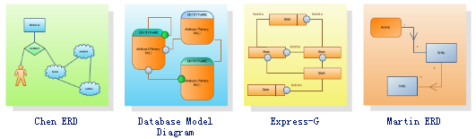
There is no standard for representing data objects in ER diagrams. Each modeling methodology uses its own notation. The original notation used by Chen is widely used in academics texts and journals but rarely seen in either CASE tools or publications by non-academics. Today, there are a number of notations used, among the more common are Bachman, crow's foot, and IDEFIX.
All notational styles represent entities as rectangular boxes and relationships as lines connecting boxes. Each style uses a special set of symbols to represent the cardinality of a connection. The notation used in this document is from Martin. The symbols used for the basic ER constructs are:
- entities are represented by labeled rectangles. The label is the name of the entity. Entity names should be singular nouns.
- relationships are represented by a solid line connecting two entities. The name of the relationship is written above the line. Relationship names should be verbs.
- attributes, when included, are listed inside the entity rectangle. Attributes which are identifiers are underlined. Attribute names should be singular nouns.
- cardinality of many is represented by a line ending in a crow's foot. If the crow's foot is omitted, the cardinality is one.
- existence is represented by placing a circle or a perpendicular bar on the line. Mandatory existence is shown by the bar (looks like a 1) next to the entity for an instance is required. Optional existence is shown by placing a circle next to the entity that is optional.
You can also use Edraw to draw Chen ERD, Database model diagram, Express-G, Martin ERD, ORM Diagram and a lot more.
Relative Database Model Diagram Resource


