UML Sequence Diagrams, Free Examples and Software Download
UML Sequence Diagrams
Sequence diagram is an interaction diagram that shows the objects participating in a particular interaction and the messages they exchange arranged in a time sequence. Use a sequence diagram to show the actors or objects participating in an interaction and the events they generate arranged in a time sequence.
Free Download UML Sequence Diagram Software and View All Examples

An all-in-one platform for 210+ diagrams.
・ Simple alternative to Visio
・ 26k+ symbols
・ 10K+ free templates
・ 10+ AI diagram generators


In EdrawMax, the UML Sequence Diagrams templates and shapes are in the Software folder.
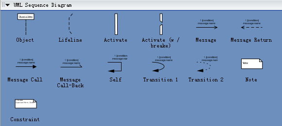
UML Sequence Diagram Drawing Elements
The following template describes the basic drawing elements used in UML sequence diagrams and when they are used. These are the diagram elements that are supported by the EdrawMax Sequence Diagram Editor tool. Some are not part of the UML specification and may not be supported by other UML tools.
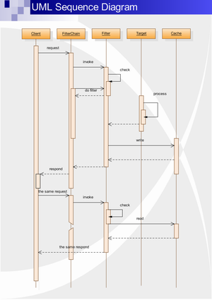
Examples of UML Sequence Diagram
EdrawMax is an optimal software to draw UML sequence diagrams.
UML Sequence Diagram Tutorial
UML sequence diagrams are used to represent or model the
flow of messages, events and actions between the objects or components of a
system. Time is represented in the vertical direction showing the sequence of
interactions of the header elements, which are displayed horizontally at the top
of the diagram.
Sequence Diagrams are used primarily to design, document and validate the
architecture, interfaces and logic of the system by describing the sequence of
actions that need to be performed to complete a task or scenario. UML sequence
diagrams are useful design tools because they provide a dynamic view of the
system behavior which can be difficult to extract from static diagrams or
specifications.
Although UML sequence diagrams are typically used to describe object-oriented
software systems, they are also extremely useful as system engineering tools to
design system architectures, in business process engineering as process flow
diagrams, as message sequence charts and call flows for telecom/wireless system
design, and for protocol stack design and analysis.
What Can Be Modeled Using UML Sequence Diagrams
Complex interactions between components. Sequence diagrams
are often used to design the interactions between components of a system that
need to work together to accomplish a task. They are particularly useful when
the components are being developed in parallel by different teams (typical in
wireless and telephony systems) because they support the design of robust
interfaces that cover multiple scenarios and special cases.
Use case elaboration. Usage scenarios describe a way the system may be used by
its actors. The UML sequence diagram can be used to flesh out the details of one
or more use cases by illustrating visually how the system will behave in a
particular scenario. The use cases along with their corresponding sequence
diagrams describe the expected behavior of the system and form a strong
foundation for the development of system architectures with robust interfaces.
Distributed & web-based systems. When a system consists of distributed
components (such as a client communicating with one or more servers over the
Internet), sequence diagrams can be used to document and validate the
architecture, interfaces and logic of each of these components for a set of
usage scenarios.
Complex logic. UML sequence diagrams are often used to model the logic of a
complex feature by showing the interactions between the various objects that
collaborate to implement each scenario. Modeling multiple scenarios showing
different aspects of the feature helps developers take into account special
cases during implementation.
State machines. Telecom, wireless and embedded systems make extensive use of
state machine based designs where one or more state machines communicate with
each other and with external entities to perform their work. For example, each
task in the protocol stack of a cellular phone goes through a series of states
to perform actions such as setup a call or register with a new base station.
Similarly the call processing components of a Mobile Switching Center use state
machines to control the registration and transfer of calls to roaming
subscribers. Sequence diagrams (or call flows as they are commonly referred to
in the telecom and wireless industry) are useful for these types of applications
because they can visually depict the messages being exchanged between the
components and their associated state transitions.
Benefits of Using UML Sequence Diagrams
These are some of the main benefits of using UML sequence diagrams.
1. Help you discover architectural, interface and logic problems early.
Because they allow you to flesh out details before having to implement anything,
sequence diagrams are useful tools to find architectural, interface and logic
problems early on in the design process. You can validate your architecture,
interfaces, state machine and logic by seeing how the system architecture would
handle different basic scenarios and special cases.
This is particularly true for systems involving the interaction of components
that are being implemented in parallel by different teams. In the cell phone
example, each task would typically be implemented by a separate team. Having a
set of sequence diagrams describing how the interfaces are actually used and
what messages/actions are expected at different times gives each team a
consistent and robust implementation plan. You can also document how special
cases should be handled across the entire system.
The very act of creating the sequence diagrams and making them work with your
architecture is valuable because it forces you to think about details such as
interfaces, states, message order, assignment of responsibilities,
timers/timeouts and special/error cases ahead of time.
2. Documentation.
Sequence diagrams can be used to document the dynamic view of the system design at various levels of abstraction, which is often difficult to extract from static diagrams or even the complete source code. The diagrams can abstract much of the implementation detail and provide a high level view of system behavior.
3. Collaboration tool.
Sequence diagrams are valuable collaboration tools during design meetings because they allow you to discuss the design in concrete terms. You can see the interactions between entities, various proposed state transitions and alternate courses/special cases on paper as you discuss the design.
In our experience, having a concrete design proposal during design meetings greatly enhances the productivity of these meetings even if the proposed design has problems. You can narrow down the problems and then make corrections to solve them. The proposal serves as a concrete starting point for the discussion and as a place to capture proposed changes.
Sequence diagram editor makes it so easy to edit your sequence diagrams that you could even make the corrections in real time during the meeting and instantly see the result of the changes as you make them.
Explore More:


