P&ID Symbols and Their Usage
Do You Want to Create Your P&ID?
EdrawMax specializes in diagramming and visualizing. This article will help you learn everything about P&ID symbols quickly. Try it free now!
In a P&ID, different shapes represent various equipment, valves, instruments, and pipelines, which are called P&ID symbols.
A piping and instrumentation diagram is more complicated than a process flow diagram. EdrawMax includes more than 2000 vector P&ID symbols used to depict mechanical equipment, piping, piping components, valves, equipment drivers, instrumentations, and controls. Get the most comprehensive collection of P&ID symbols from our pre-defined library.
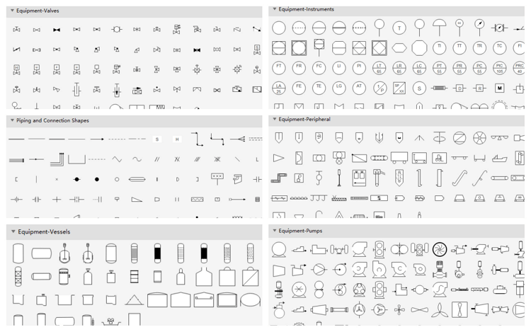
The common P&ID symbols are listed here:
Part 1: P&ID Equipment Symbols
Pumps and tanks come in a variety of designs and shapes. You can choose from abstract symbols and simulation images. Learn the basic knowledge about piping and instrumentation diagrams.
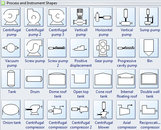
A pump is a mechanical device that uses suction or pressure to raise or move liquids, compress gases, or force air into inflatable objects such as tires. Pump symbols may closely resemble those for compressors.
A centrifugal pump is a rotodynamic pump that uses a revolving impeller to add to the force and pressure of fluids.
The gear pump provides continuous, non-pulsing flow, making it ideal for chemical installations.
A sump pump is widely used to remove accumulated water from a sump pit or other location.
The vacuum pump is applied to improve the efficiency of steam heating systems in many ways. The most important consideration is the rapid and efficient removal.
The screw pump is the Archimedes screw pump that is still used in irrigation and agricultural applications.
Tank is for storing process fluids of various types under different process conditions.
An onion tank refers to an open-top collapsible bladder designed for mobile storage when recovering contaminants.
A compressor is a mechanical device that takes in a medium and compresses it to a smaller volume. A mechanical or electrical drive is typically connected to a pump that compresses the medium.
An axial compressor is widely used in gas turbines, such as jet engines, high-speed ship engines, and small-scale power stations.
A reciprocation compressor is typically used where high compression ratios are required per stage without high flow rates, and the process fluid is relatively dry.
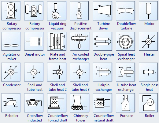
A rotary compressor is a type of gas compressor that uses a rotary-type positive-displacement mechanism.
Mixing is a device that combines or puts some materials together to form one substance or mass.
A mixing vessel is a container that is used to blend several components.
A heat exchanger is a device used to transfer heat energy between two process flows. It transfers heat energy through conductive and convective heat transfer.
Cooling towers transfer heat energy to the outside air through evaporation.
A cooler is a device, container, or room that cools air through the evaporation of water or keeps air cool.
Turbine driver is used to drive pumps and fans at petrochemical plants.
A furnace is a device for heating a continuous current of air using a fire contained within the apparatus without mingling the fresh air with the combustion products.
The boiler is a closed vessel where water or other fluid is heated.
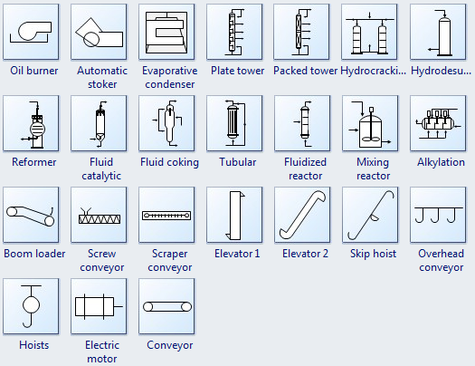
The oil burner is engineered from the ground up exclusively to burn waste oils.
Automatic stoker is applied to supply hot water to central heating systems.
Plate towers are used extensively in many processes and industrial applications.
A packed tower is a packed bed used to perform separation processes.
The elevator is used to control the position of the nose of the aircraft and the angle of attack of the wing.
A mixing reactor is widely used in the chemical industry to promote mixing.
Part 2: P&ID Valves Symbols
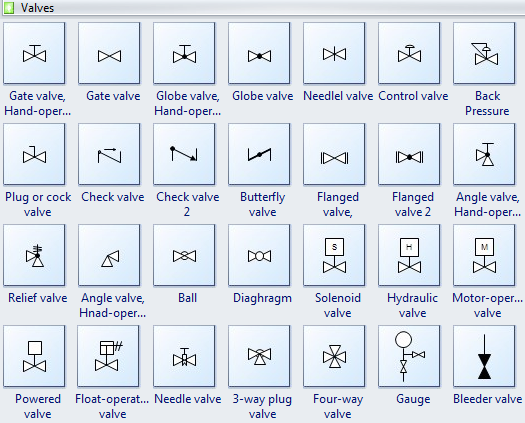
A gate valve is a device that controls the flow of liquids and gases.
A check valve, also known as a one-way valve, prevents the line of medium back.
A Globe valve is a mechanism to control or stop the liquid or gas flow through a pipe.
The ball valve has a spherical disc, the part of the valve that controls the flow through it.
A butterfly valve is installed between two flanges using a separate set of bolts for each flange.
The angle valve is oriented at an angle of 90 deg of the gate valve.
Part 3: P&ID Piping Lines Symbols
Process flow diagrams use memorable piping lines to represent signals transmitted between equipment. These symbols identify how the process instruments connect and what type of signal is being used (electrical, pneumatic, data, etc.).
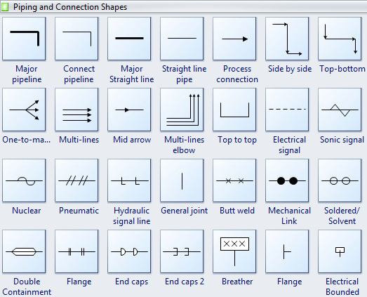
The major pipeline is used to connect the equipment in any position.
A central straight line connects the equipment in the same horizontal or vertical position.
Process connection helps to create the process flow between equipment. Double the process connection to edit the description.
Part 4: P&ID Instruments Symbols
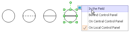
The process flow diagram uses symbols and circles to represent each instrument and its interconnectedness.
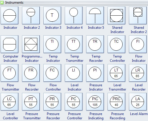
These instrumentation symbols can easily change types by clicking the quick action button while designing.
With large pre-drawn examples and more than 8500 symbols, drawing couldn't be easier! Click here to learn more about Process and Instrument Diagram Symbols.
Learn how to create a piping and instrumentation diagram here. Watch the video below and learn how to make a P&ID with professional software in minutes!
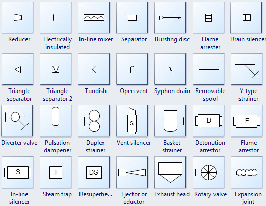
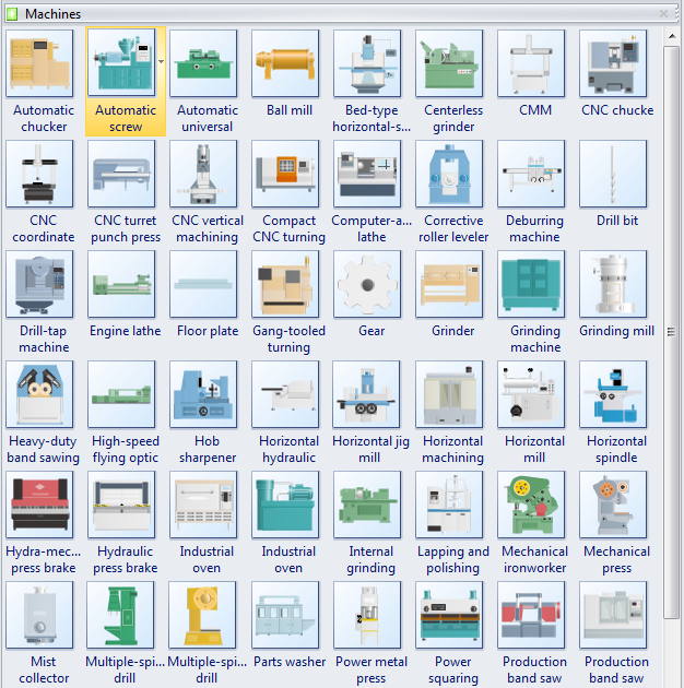
Part 5: More P&ID Symbols - Simulation Images
P&ID Designer includes lots of lifelike images, enabling presentation-quality diagrams. View manufacturing flow chart symbols.

An all-in-one platform for 210+ diagrams.
・ Simple alternative to Visio
・ 26k+ symbols
・ 10K+ free templates
・ 10+ AI diagram generators


More Related
P&ID Software for Linux - Easy Piping and Instrumentation Diagram Program


