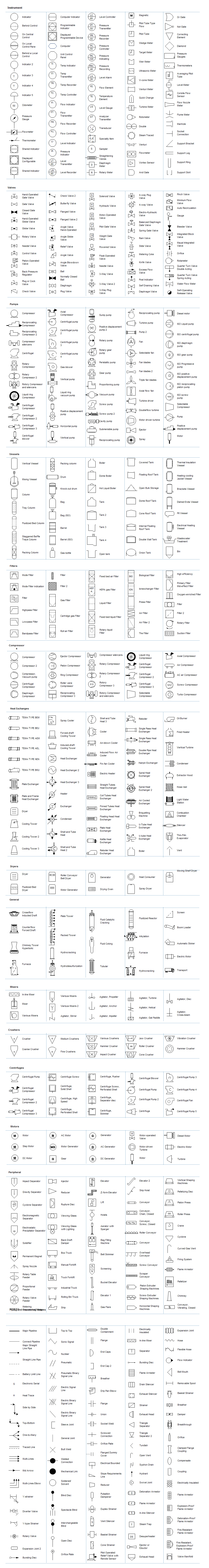
P&ID Symbol Legend
Piping & Instrumentation Diagram (P&ID) is a graphical and schematic representation of the functional relationship between piping, instrumentation, and system equipment components used in the field of automation and instrumentation. There are usually mostly made and used by engineers designing a manufacturing process for a particular physical plant.
Piping and Instrumentation Diagram Symbols Detailed Documentation provides a rich set of shapes & symbols for documenting P&ID and PFD, including shapes for the instrument, valves, pump, heating exchanges, mixers, crushers, vessels, compressors, filters, motors, and connecting shapes.
Symbols Used in P&IDs
P&ID components are represented by several standard symbols, which are not to scale, nor are their dimensions accurate. The symbols are always labeled using words, letters, and numbers to better identify and specify the components being represented. Furthermore, one should consider that these diagrams don't always represent the targeted physical locations nor the proximity of each component involved. These symbols' main function is to illustrate the system's process rather than serve as a map.
Free Download P&ID Symbol Legend PDF File
Free Download P&ID Software and Get Editable Symbols
Where to find all P&ID symbols?
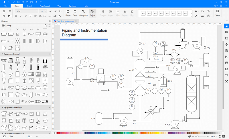
With EdrawMax, you would be exposed to a broad range of different P&ID symbols as well as a variety of their templates. This diagramming tool also offers an amazing interface with drag-and-drop intuition along with preset drawing symbols that make it much easier to create your own P&ID diagrams. You can locate the predesigned P&ID symbols under the Industrial Automation & PID category from the EdrawMax library.

An all-in-one platform for 210+ diagrams.
・ Simple alternative to Visio
・ 26k+ symbols
・ 10K+ free templates
・ 10+ AI diagram generators


When you get into the workspace of EdrawMax, the library will open the left side of the canvas. You can find all the predesigned P&ID symbols under the Industrial Automation and P&ID category, which will be used for representing the functional relationships between piping, instrumentation, and system equipment units.
How to create a P&ID diagram with P&ID symbols?
Watch the video below to know how to use P&ID symbols and make a P&ID with EdrawMax.
Tips on creating a P&ID diagram
There are some basic steps that you can follow when creating a P&ID through computer software, including:
1. Develop and confirm an equipment list using the library's symbols after being certain about the list.
2. Connect the necessary pipes and equipment and review the details. You can go over the process a couple of times with a colleague to search for any imperfections.
3. Share your creation with collaborators.
More Related


