Circuit Diagram
- Part 1: What Is a Circuit Diagram
- Part 2: Purpose and Benefit of Circuit Diagram
- Part 3: Symbols and Icons of Circuit Diagram
- Part 4: What to Do Before Creating a Circuit Diagram?
- Part 5: How to Make a Circuit Diagram in EdrawMax?
- Part 6: Tips for Making Circuit Diagram
- Part 7: Example
- Part 8: Conclusion
Part 1: What Is a Circuit Diagram
A circuit diagram is a visual representation of a complete circuit of an electronic or electrical equipment. The illustration is populated with several globally recognized symbols and icons representing the components that are connected with the help of the lines in order to work collectively to perform a particular task.
Part 2: Purpose and Benefit of Circuit Diagram
As mentioned earlier, the purpose of a circuit diagram is to give the engineers and designers detailed information about how the components of an electrical/electronic appliance must be connected so it can work correctly after assembling. Because such a drawing has all the icons and symbols that represent the real components, it becomes easier for the analysts and manufacturers to read the diagram, and prepare the equipment accordingly.
The major advantage of preparing a circuit diagram before jumping into the assembling of the circuit itself is that the illustration helps the engineers perform dry runs, assess the inconsistencies in the circuit, and make the required changes on the paper itself. This saves their decent amount of time, and prevents financial wastage that would otherwise occur if the hit-and-trial method was used during the manufacturing process.
Part 3: Symbols and Icons of Circuit Diagram
Because several components of varied specifications are present in a circuit to make the equipment function as expected, their globally recognized symbols vary as well. Some of the commonly used icons that you will find in almost every circuit diagram are given below along with their brief description:
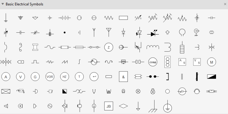
Circuits and Logic Diagram Symbols
The circuits and Logic template helps you create relatively complex circuit diagrams for any use. You can create both analog and digital circuitry using the Analog and Digital Logic, Integrated Circuit Components, Terminals and Connectors, and Transmission Paths stencils. This is a good circuits tool for playing with an idea, fleshing out a concept, or discussing a technical issue with someone else. It provides all the necessary circuits symbols that are needed to create basic circuitry and a number of standard Integrated Component (IC) shapes.
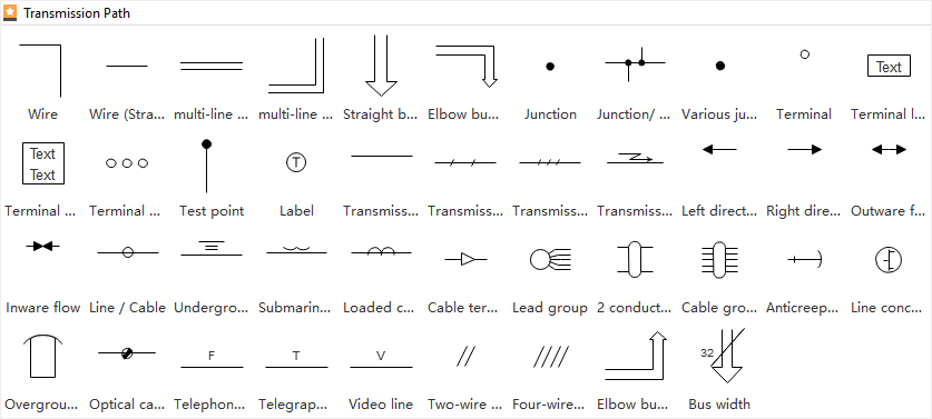
Transmission Path
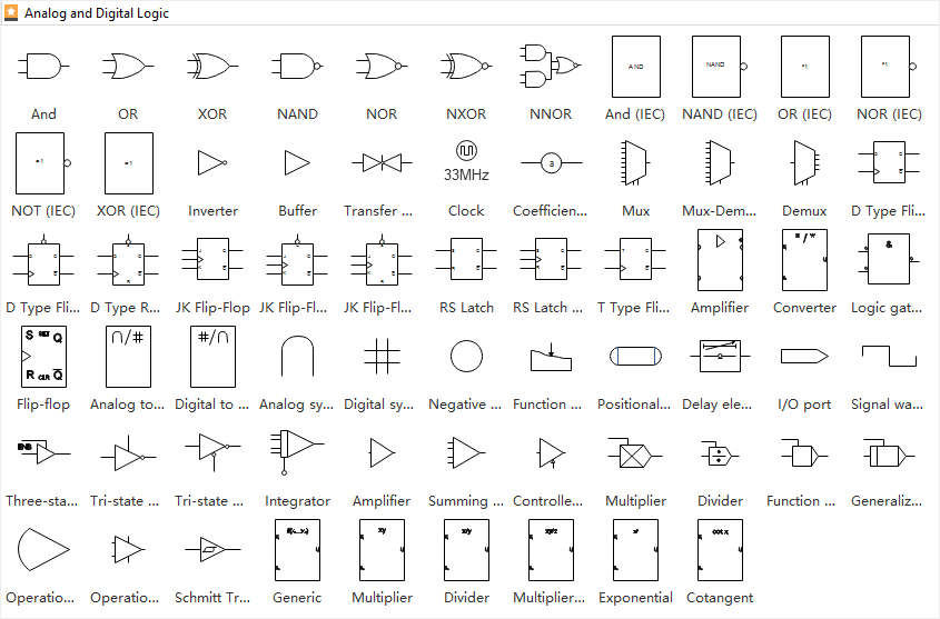
Analog and Digital Logic
The following analog and digital logic shapes include inverter, buffer, clock, function generator, amplifier, converter and more circuits symbols.
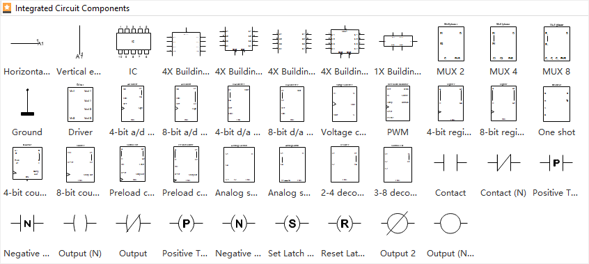
Integrated Circuit Components
The following integrated circuit components shapes include building block, board, switch point, driver, extension and more circuit component symbols.
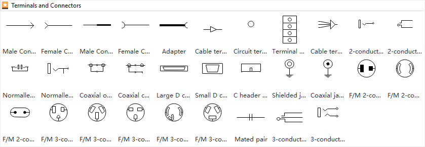
Terminals and Connectors
The following terminals and connectors shapes include contact, circuit terminal, conductor, cable and more circuit connectors symbols.
Part 4: What to Do Before Creating a Circuit Diagram?
A circuit diagram is needed before you manufacture an actual circuit alright. However, there are few things that you require even before preparing a circuit diagram. The most important points that you must keep in mind include:
- Proper Understanding
- Readability
- Designers’ Techniques
- Use a Software
You must have a proper and in-depth understanding of how the circuits work, and how the components would behave when connected to form a circuit. Incomplete or absolute lack of knowledge might result in severe damage to the organic and non-organic bodies during the practical implementation.
You must be able to read and recognize the symbols that are used in a circuit diagram. This way it would be easier for you to place the required components of precise specifications on the canvas (or draw them on a sheet of paper) correctly, thus coming up with a flawless illustration.
Although there are many engineers out there who can design a functioning circuit, there are merely a few who are able to get the job done efficiently, i.e., connecting the components effectively enough to extract the maximum from the circuit. Make sure to be the one who delivers efficient output.
Even if you are well-aware of the symbols and icons used in a circuit diagram, drawing one on paper would be extremely time-consuming and tedious. Therefore, it is a good idea to use an efficient program like EdrawMax by Wondershare that not only simplifies the chart preparation task, it also helps you pick and use the correct symbols to produce a professional illustration.
Part 5: How to Make a Circuit Diagram in EdrawMax?
As mentioned earlier, Wondershare EdrawMax makes your drawing creation task easier. This is because it is populated with several categories for various industry types, where each category has multiple templates to help you start your diagramming projects.
With that said, you can follow the instructions given below to learn how to draw a circuit diagram using Wondershare EdrawMax:
Step 1: Pick a Suitable Template or Start from Scratch
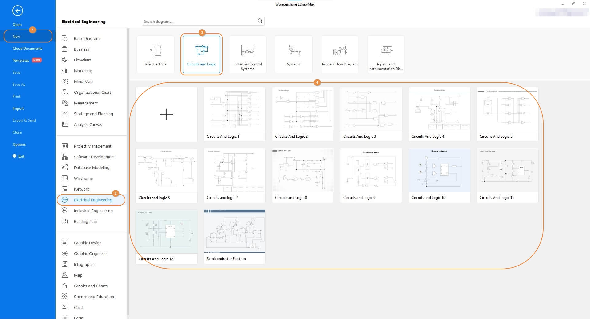
Launch Wondershare EdrawMax on your computer, make sure that New is selected in the navigation bar on the left, and select the Electrical Engineering industry from the middle pane. From the upper row of the right window, choose Circuits and Logic, and pick your preferred template from the lower section. Note: Because every circuit diagram has a different architecture, as an engineer it would be wise if you start drawing the illustrations from a black project. You should pick a template to begin with only if the circuit you are planning to create is a common one.
Step 2: Customize the Circuit Diagram
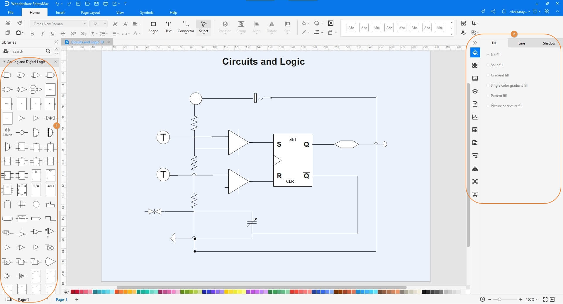
Double-click any of the component symbols on the canvas and change its caption as needed. Next, drag the other icons representing the components from the libraries on the left to the canvas, and name them accordingly. Optionally use the tools and options in the right pane to decorate the symbols if required.
Step 3: Save and Export the Circuit Diagram
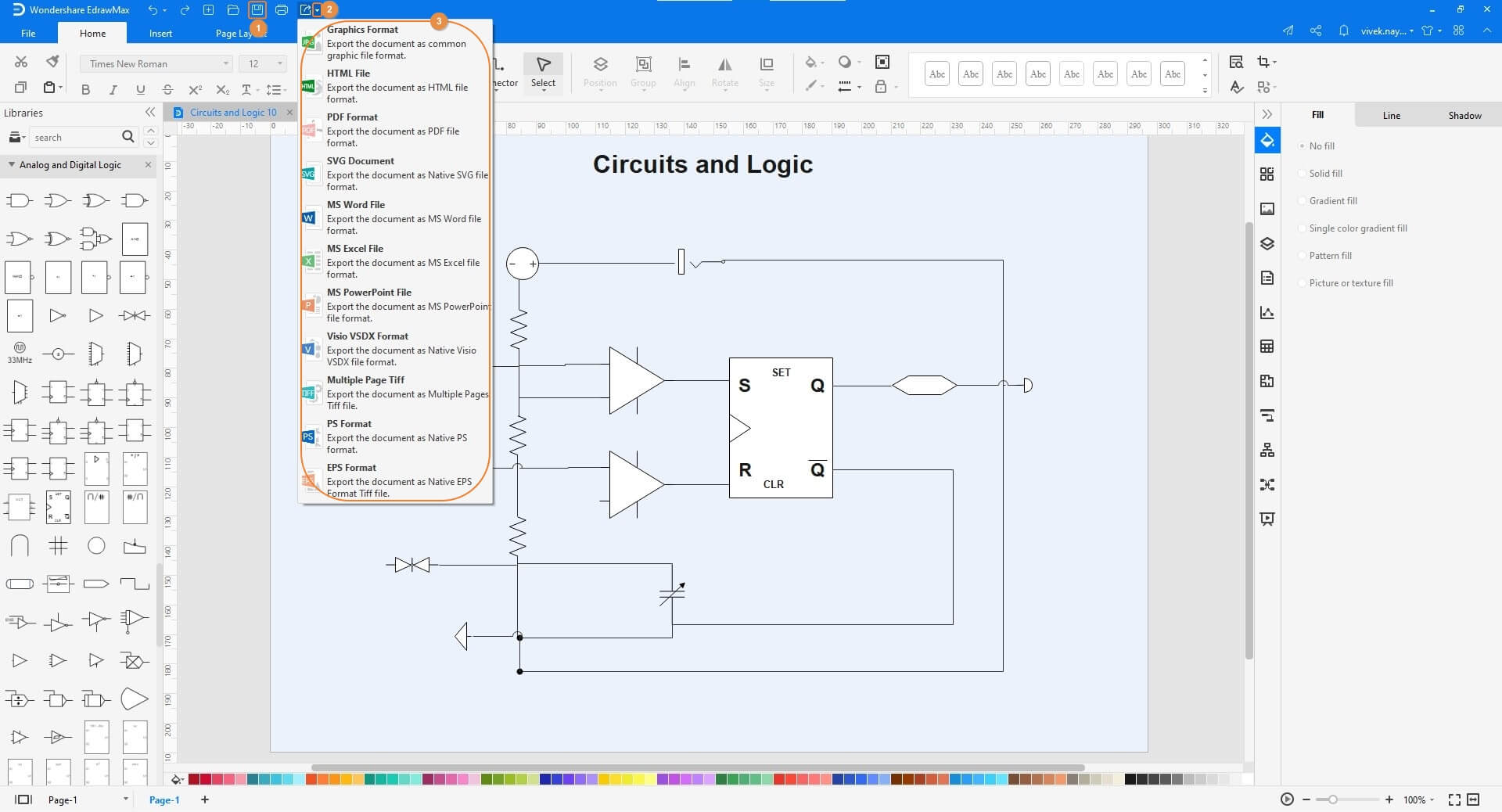
Click the Floppy (Save) icon present in the quick access toolbar at the top-left corner of the window. After this, click the More button on the Export icon, and when the menu appears, choose your preferred format to export the circuit diagram in.

An all-in-one platform for 210+ diagrams.
・ Simple alternative to Visio
・ 26k+ symbols
・ 10K+ free templates
・ 10+ AI diagram generators


Part 6: Tips for Making Circuit Diagram
A couple of pro tips that might come in handy while creating a circuit diagram include:
- Use large symbols that are easy to read. Use more space if need be
- Avoid congesting the diagram by populating it with too many icons. If the circuit is complex, and several components are to be added to it, draw one unit at a time, and use the connector lines to illustrate the connection between multiple units to form a complete circuit
- Be precise while naming the components and adding their specifications. Incorrect names and/or specifications might result in production of a non-working equipment
- Perform several dry runs before you start assembling the circuit to avoid the wastage of time and finances
Part 7: Example
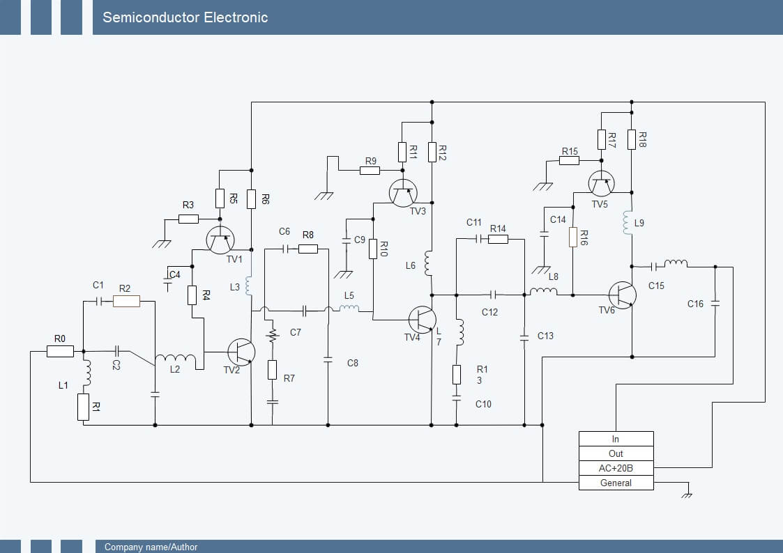
The above diagram is that of a semiconductor electron that has several capacitors, resistors, and the symbols of other important components to form a fully functional circuit. The icons of the components in the circuit diagram have certain captions with numbers that represent their corresponding specifications. This helps in the process of manufacturing a working appliance.
Part 8: Conclusion
A circuit diagram is essential before the actual circuit is assembled with the required components. While drawing an illustration manually is one of the methods, it would be wise to use an efficient diagramming tool such as Wondershare EdrawMax that simplifies your task, and also lets you add the correct symbols and icons from the built-in libraries, thus significantly expediting your overall process.


