What is a Fault Tree Analysis (FTA)? - The Beginner's Guide
Contents
What is a Fault Tree Analysis (FTA) - Definition
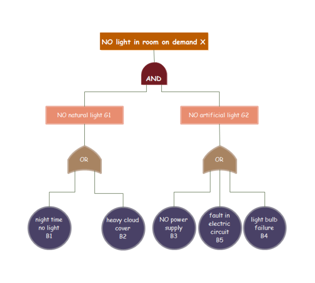
The fault tree analysis is a deductive process. Developers or engineers use it to find out the root cause or human errors for different types of software, engineering facilities or hardware. It usually starts at a single point (the undesired top-level event) and then goes downwards in the form of a tree (the top-down structure) with a number of blocks and symbols to show the relationship between events (mechanical components). More specifically, the definition of "Fault" in fault tree analysis indicates the occurrence of an undesired state for a component or system. For example, the light is failed off due to the switch failure as shown below.
Furthermore, the term "Fault" has the following three key types:
- Primary Fault - A component failure that cannot be further defined at a lower level of a system;
- Secondary Fault - A component failure that can be further defined at a lower level, but with limited details;
- Command Fault - A state that is commanded by an upstream failure.
History of Fault Tree Analysis
The development of fault tree analysis has the following main stages:
- The Early Years - In 1961, Bell Labs developed the model for the use of Air Force Minuteman Launch Control System. Later, Boeing company use the fault tree analysis model for the design and evaluation of both civil aircraft and commercial aircraft. Around the 1970s, engineers in the aerospace and nuclear power industries further adopted the fault tree analysis model for complex projects.
- The Middle Years - Fault tree theory became popular among different countries with the adoption of technical algorithms and codes. Around the 1990s, the software industry and the chemical sector also introduced fault tree analysis.
- The Recent Years - Worldwide professionalists developed more commercial codes for the use of reliability engineering and robotics projects. Now, fault tree analysis is regarded as one of the most significant system reliability and safety analysis tools.
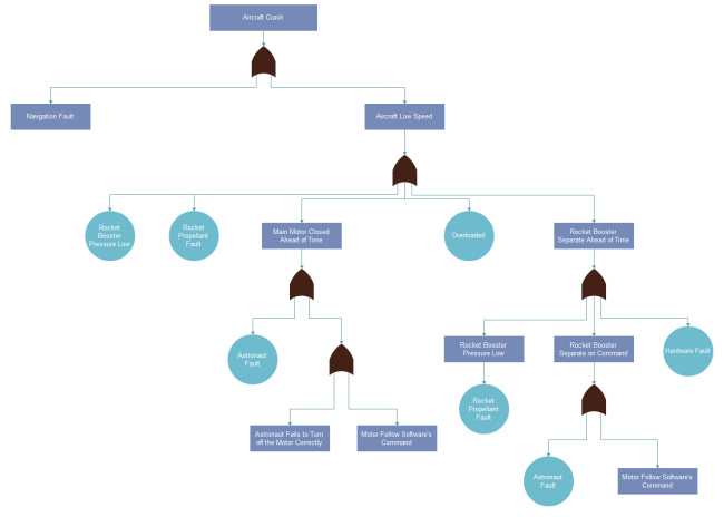
Here is a fault tree analysis example for finding out the cause of aircraft crash. Feel free to click on it to see more information.
Why Use Fault Tree Analysis?
Overall, it offers a well-structured, highly visual and comprehensive picture of your system. It helps users or developers quickly understand the results based on the logical relationships in order to pinpoint drawbacks and errors in the design process. Some other important benefits are:
- Easy to Adopt - Administrators can easily make changes for their system, evaluate for possible effects, design quality test and maintain procedures according to their fault tree analysis diagrams.
- Wide Applicability - Many subjects and fields use fault tree analysis, such as organizations in hardware, software, algebra, probability, reliability, physics, chemistry and engineering sectors etc.
- Risk Estimation - Engineers or developers can identify risks prior to a program launch by using the fault tree analysis model.
- For Complex System - It can be used to monitor and manage the safety performance of large-scale complex systems, for example, the fuel and aircraft project.
Fault Tree Analysis and other Analytical Models
Developers often compare the fault tree analysis, the Failure Mode Effects Analysis (FMEA) and the Reliability Block Diagram (RBD):
Relationship with FMEA
- Fault tree analysis is in the form of a top-down tree, while FMEA usually has a matrix structure with all the key measurements (severity rating, occurrence rating, process controls, detection rating and risk priority number etc.) right on the top column.
- Fault tree analysis can be used to show single or multiple initiating faults, but it could be hard to find all possible faults by using fault tree analysis. In contrast, FMEA does well in exhaustively cataloging initiating faults and identify effects, but not good at exploring multiple or single faults.
- In some cases, FTA and FMEA can be used at the same time for a better system development (e.g. the analysis of civil aerospace).
Relationship with RBD
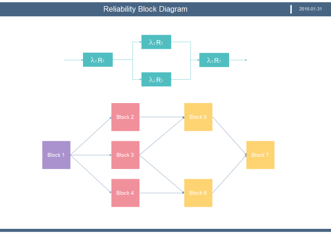
- RBD depicts a system by using paths rather than gates in fault tree analysis diagrams.
- RBD focuses on the success part while fault tree analysis works on the failure part.
- Fault tree analysis is normally used for analyzing fixed probabilities of the occurrence of each event. RBDs may cover time-varying factors during the analysis process.
Fault Tree Analysis Diagram Symbols
Fault tree analysis has three basic symbol types: events and gates symbols.
Events
This sub-category includes the following shapes:
- Primary/basic event is normally shown as a circle. It is a failure or error in a system component or element.
- External event is normally shown as a house-shape. It is an event that normally expected to occur.
- Undeveloped event usually means some component in a system that needs no more investigation due to limited information.
- Conditioning event is a restriction on a logic gate.
- Intermediate event is usually placed above a primary event in order to show more event description details.

Gates
These symbols mainly show the relationship between output and input events, and the two most popular ones in this sub-category are OR gate and AND gate.
- OR gate - It occurs as long as at least one of the input events occurs.
- AND gate - It occurs only if all input (at least two) requirements are met.
- Exclusive OR gate - It occurs only if one of the input conditions is met, not if all conditions are met.
- Priority AND gate - It occurs only after a specific order of conditions.
- Inhibit gate - It only occurs if all input events take place and whatever is defined in a conditional event.

More Fault Tree Analysis Diagram Symbols
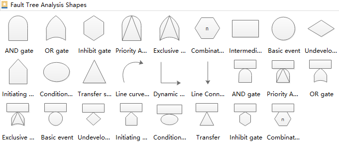
Here you can see more fault tree analysis diagram standard symbols including the transfer type and the line type etc.
How to Undertake a Fault Tree Analysis?
Although the nature of the undesired event may be quite different, fault tree analysis has the same procedure for any types of undesired event. To do a comprehensive fault tree analysis, simply follow the process below:
1. Define and identify the fault condition (hazard) as precisely as possible based on the aspects such as the amount, duration, and related impacts etc.
2. Using technical skills and existing facility details to list and decide all the possible reasons for the failure occurrence.
3. Break down the tree from the top level according to the relationship between different components until you work down to the potential root cause. The structure of your fault tree analysis diagram should be based on the top, middle (subsystems), and the bottom (basic events, component failures) levels.
4. If your analysis involves the quantitative part, evaluate the probability of occurrence for each of the components and calculate the statistical probabilities for the whole tree.
5. Double-check your overall fault tree analysis diagram and implement modifications to the process if necessary.
6. Collect data, evaluate your results in full details by using risk management, qualitative and quantitative analysis to improve your system.
What else Should You Consider When Doing Fault Tree Analysis?
If you want to efficiently undertake or improve your fault tree analysis process or diagram, just have a try for the following tips:
- Leave more space for further tree expansions or possible changes in your fault tree analysis diagram.
- Make sure that your top undesired event is reasonable. In this case, you can test potential results against the original problem, or do peer review to make an adjustment.
- Use correct symbols according to their specific meanings.
- Offer a detailed description of your event text and avoid general words such as "failure" or "fault" when explaining your component problem.
- Your analysis team should include the system design engineer, the reliability engineer and the system data analyst with an engineering background for the study of your system.
- One fault tree diagram can only be used to apply for one undesired event analysis.
- Label your causes in different color codes to easily identify risk levels: red for critical risk, orange or yellow for high risk, and green for low risk etc.
More Free Fault Tree Analysis Templates
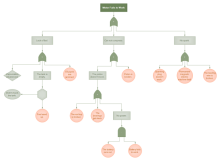
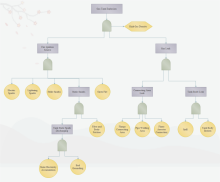
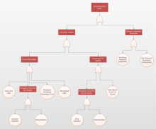
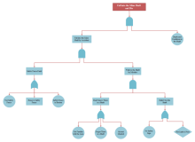
The best way to learn fault trees analysis model is to check out some easy fault tree templates. Free feel to click on any of these fault tree templates below to see more details or download them for free.
|
|
|
| Motor Fail FTA Diagram | Tank Explosion FTA Diagram | Quenching Burn FTA Diagram |
|
|
|
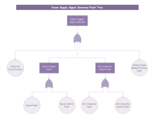
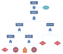
| Mine FTA Diagram | Power Signal FTA Diagram | Scaffolding Fall FTA Diagram |
How to Create a Fault Tree Analysis Diagram?
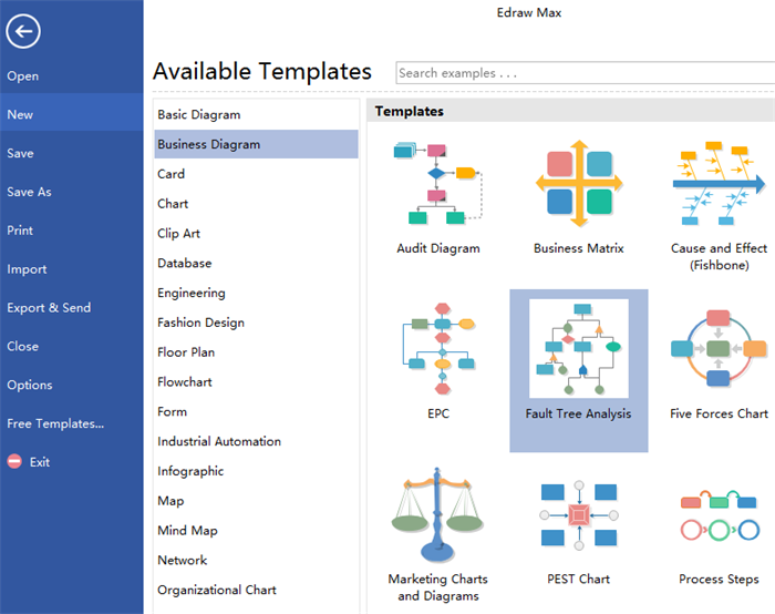
First, you have to download a powerful diagramming software.
Creating a fault tree analysis diagram is easier than you think. Just do the following steps:
Step 1: Open a Blank Page
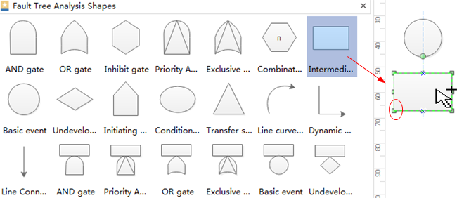
Step 2: Add Shapes
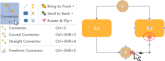
Step 3: Connect Shapes
Step 4: Add Text
Step 5: Further Customize Your Shapes
Step 6: Save, Print and Export Your Work
FTA Diagram Software Recommendation
Read More:
See the Key Difference Between Fault Tree Analysis and Event Tree Analysis
