Ladder Diagram
Part 1: What Is a Ladder Diagram?
A ladder diagram comprises ‘rails’ that are two parallel lines drawn vertically and represent power supply, and ‘rungs’ that are several lines drawn horizontally with various symbols to connect the ‘rails’ to form an illustration of a control circuit. With that information, in a nutshell, a ladder diagram, as mentioned earlier, is a drawing of the logical structures of industrial equipment that is prepared to understand how the machine would behave when it is turned on or activated.
Part 2: Purpose and benefit
The main goal of a ladder diagram is to help the designers prepare a Programmable Logic Controller (PLC) application that could be used to control heavy-duty industrial machinery. Such units can be either quite simple or highly advanced and capable of performing highly sophisticated tasks merely with the help of a button or switch.
The most significant advantage of having a ladder diagram is that it helps draw and understand the logical structures of the electrical circuits quite quickly, without going through a steep learning curve. Another benefit of such a drawing is that it can illustrate digital logic pretty clearly and intuitively.
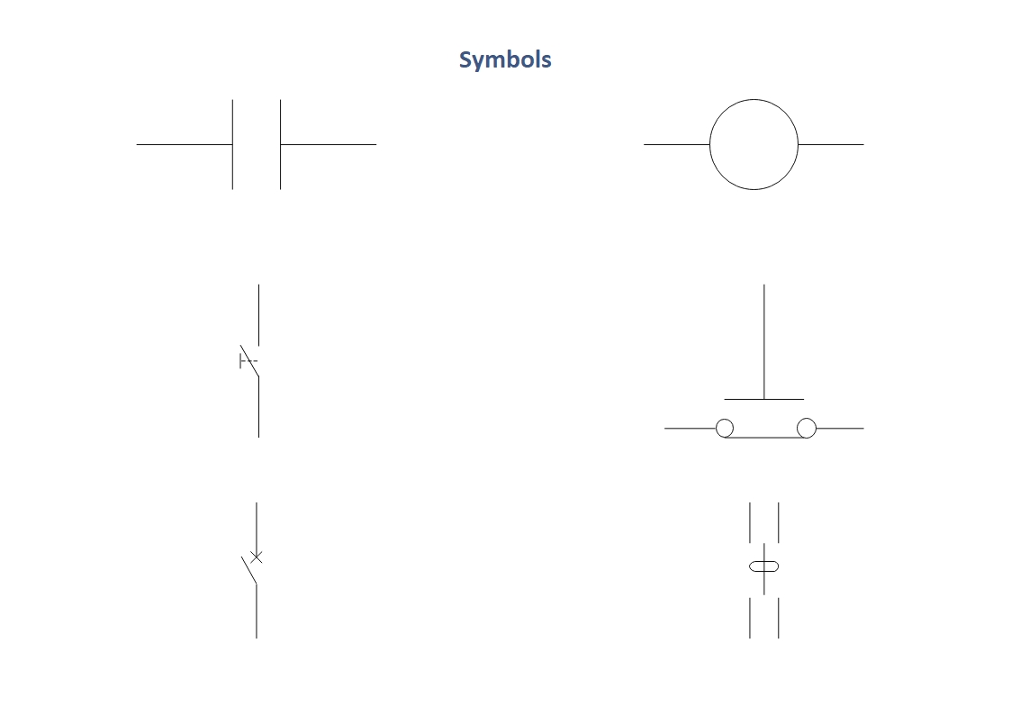
Part 3: Symbols Used in a Ladder Diagram
Reading a ladder diagram solely depends on how accurately and minutely you can identify the symbols and icons that have been used to draw the illustration. Some of the most common signs that you will likely see in a typical ladder diagram are listed below:
Part 4: What to Do Before Creating a Ladder Diagram?
There are specific prerequisites that must be met before you can start working on a ladder diagram to make the entire chart fruitful that can produce a fully functional logical structure upon practical implementation. A couple of such requirements are listed below:
- Understanding the Input Types
- Understanding the Possible Outputs
- Knowing the Ingredients
- Thorough Understanding of Circuits and Industrial Equipment Structures
- Use a Drawing Tool
The inputs in a piece of industrial equipment are usually manual such as a push-button, a switch, or something similar to this. While drawing a ladder diagram, these input types can be illustrated with the help of their corresponding symbols.
A digital circuit can produce only one of the two outputs, namely 0 or 1, and it is imperative to understand the nature of both of them before you start diagramming. While the 0 output reflects a negative value or 'Off' state, the 1 represents the positive state or 'On.' Other possible labels reflecting the identical values that you may notice in a typical ladder diagram could be 'Yes' or 'No,' 'Tall' or 'Low,' or 'Real' or 'Negative.' The effect of any of the output states is that the machine/equipment is either switched off (inactive) or turned on (active).
A ladder diagram has 'rails' that are two parallel lines drawn vertically and several 'rungs' that are the horizontal lines with various symbols that connect the ‘rails’, thus forming the shape of a ladder.
It is essential to have an in-depth understanding of how the circuits and industrial equipment structures work. Any professional with an engineering degree or diploma in industrial automation would draw a ladder diagram and take it to the implementation stage quite quickly.
This goes without saying. Although it is possible to draw a blueprint of a structure manually, with all the advanced programs available in the market today, you can use any sophisticated diagramming application like EdrawMax by Wondershare to simplify and expedite the ladder diagram creation task.
Part 5: How to Make a Ladder Diagram in EdrawMax?
Wondershare EdrawMax is a complete diagramming tool to create vector-based illustrations and charts for various industries, including computer networks, software development, buildings, organizational charts, and much more. To learn how to draw a ladder diagram with EdrawMax, you can follow the instructions given below:
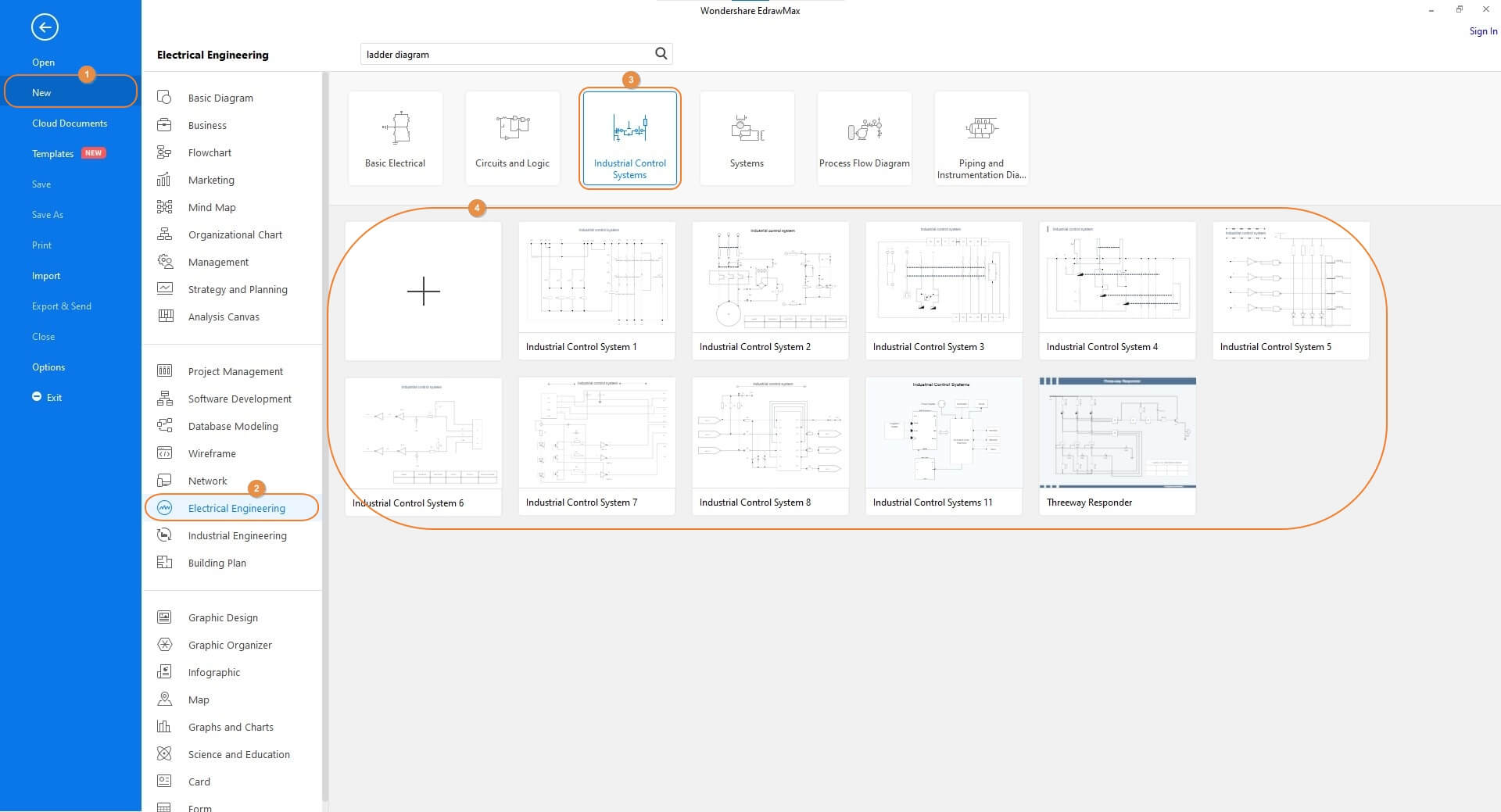
Step 1: Pick a Correct Template
After downloading, installing, and launching Wondershare EdrawMax on your computer, confirm that New is selected in the navigation pane on the left and select the Electrical Engineering industry from the center pane. From the right window, click to choose Industrial Control Systems from the Categories row at the top, and then choose your preferred template from the lower section.
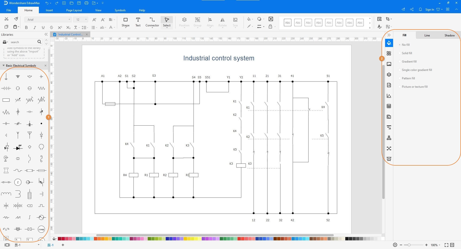
Step 2: Modify the Diagram
Drag the symbols from the libraries on the left to the Canvas to make the required amendments to the template. You can also use the tools and options on the right to format the shapes to make the illustration more presentable.
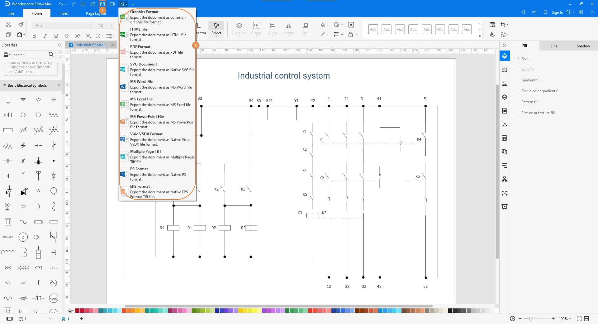
Step 3: Save and Export the Final Illustration
Once the ladder diagram is complete, click the Save button from the quick access toolbar present at the top-left corner of the interface. After this, click the More button on the Export icon, and choose your preferred format to export the drawing, and save it on your local computer.

An all-in-one platform for 210+ diagrams.
・ Simple alternative to Visio
・ 26k+ symbols
・ 10K+ free templates
・ 10+ AI diagram generators


Part 6: Tips for Making Ladder Diagram
A few pro tips that you may want to keep in mind while preparing a ladder diagram include:
- Avoid drawing small icons to save space. Significant symbols are clearer to understand
- Have a good understanding of the symbols used in ladder diagrams to avoid any confusion or miscalculation
- Make the illustration spacious enough to accommodate the labeling and brief description to make it easy for the implementers to understand the diagram.
- Consult experienced engineers wherever needed while preparing the diagram to eliminate the chances of ending up having wrong circuits and faulty connections
Part 7: Examples of Ladder Diagram
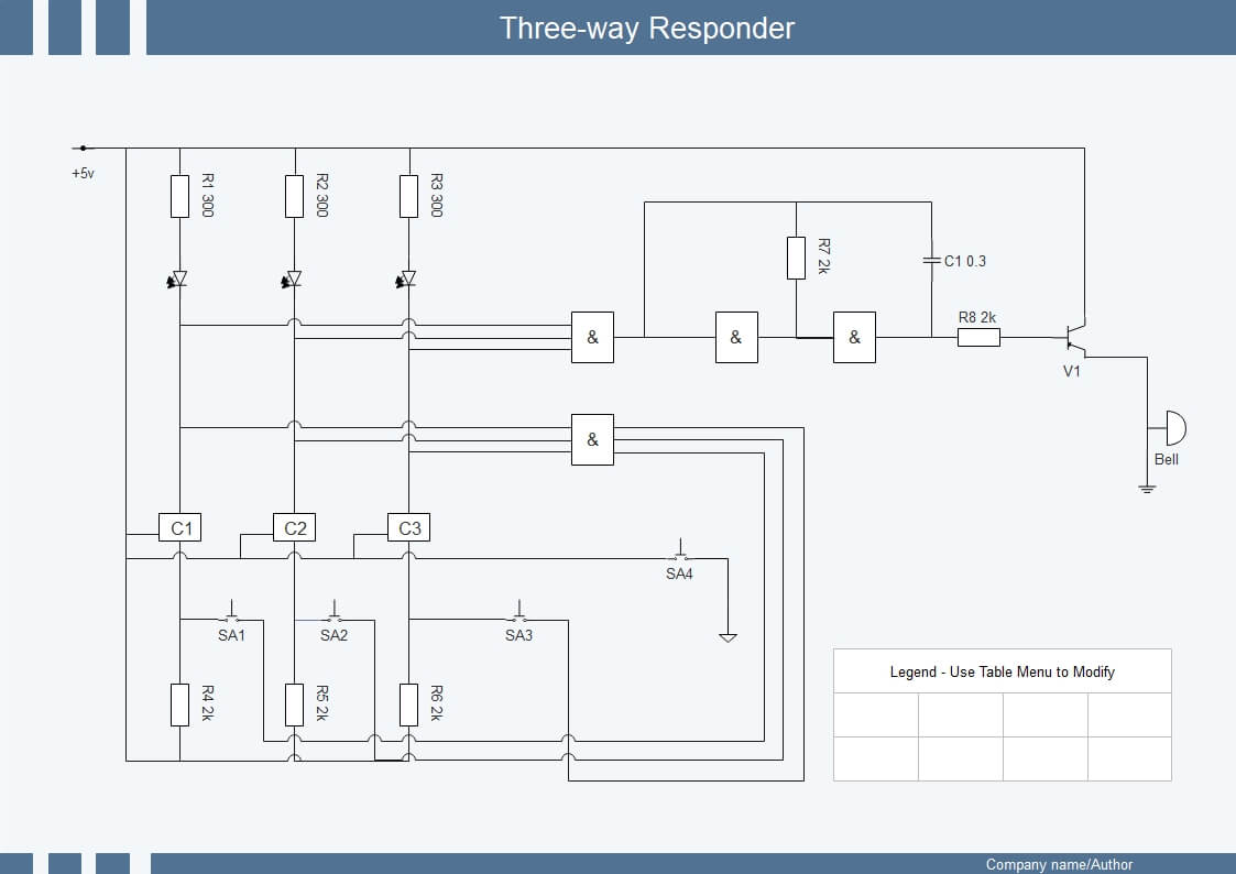
The above ladder diagram can be used to prepare a three-way responder that accepts +5 volts as input. Also, one end, the negative port, of the bell on the right is grounded that helps in making the circuit function properly without breaking down any component that the equipment has. The ‘Legend’ present at the bottom-right corner can be used for labeling to help the designers and engineers make the drawing understandable for everyone.
Part 8: Conclusion
A typical ladder diagram consists of ‘rails’ and ‘rungs’ that are two parallel lines drawn vertically and multiple horizontal lines that connect the ‘rails’ at different instances, respectively. Because such an illustration roughly forms the shape of a ladder, the diagram is called so. Such a chart is helpful to prepare industrial structures where the programmable logic controllers are used. Although making such a vector portrayal is time-intensive, an efficient program like Wondershare EdrawMax can expedite and simplify the creation process.


