Process and Instrument Diagram Symbols
Edraw process and instrumentation templates include lots of process and instrumentation shapes, centrifugal pump, vertical pump, horizontal pump, vertical pump, sump pump, vacuum pump, screw pump, positive displacement pump, etc. These shapes will facilitate the improvement of your drawing level.
Process Flow Diagram Symbols - Process and Instrumentation Shapes
Process and Instrument Diagram Shapes
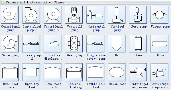
Centrifugal pumps are used to transport fluids to the hydrodynamic energy of the fluid flow. Centrifugal pump converts the input power to kinetic energy in the liquid by accelerating the liquid by an impeller.
Sump pump is a pump used to remove water that has accumulated in a water collecting sump basin, commonly found in the basement of homes. Sump pumps help keep your basement or crawlspace dry.
Vacuum pump is a device that removes gas molecules from a sealed volume in order to leave behind a partial vacuum
Screw pump is a positive displacement pump that use one or several screws to move fluids or solids along the screw axis.
Gear pump uses the meshing of gears to pump fluid by displacement.
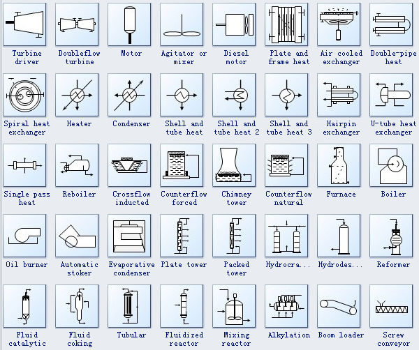
Motor is a device that creates motion. It usually refers to an engine of some kind.
Heater is an object that emits heat or causes another body to achieve a higher temperature.
Condenser is a device for reducing a gas or vapor to a liquid.
Furnace is a device used for heating. The name derives from Latin fornax, oven.
Boiler is a closed vessel in which water or other fluid is heated. The fluid does not necessarily boil.
Oil burner is a heating device which burns fuel oil. The oil is atomized into a fine spray usually by forcing it under pressure through a nozzle
Tubular refers to the form of a cylinder or tube.
Process Flow Diagram Symbols - Piping and Connection Shapes
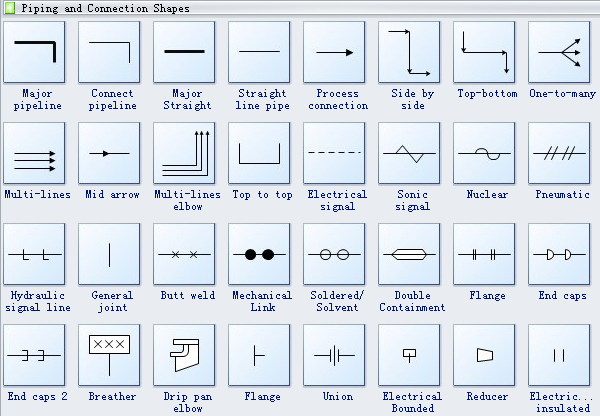
Flange is a projecting flat rim, collar, or rib on an object, serving for strengthening or attachment or (on a wheel) for maintaining position on a rail.
Reducer is the component in a pipeline that reduces the pipe size from a larger to a smaller bore (inner diameter).
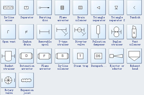
Separator refers to a mechanical device to separate fluids and solids.
Steam trap is a device used to discharge condensate and non condensable gases with a negligible consumption or loss of live steam.
Need fresh looking process and instrument diagram symbols for your design? These process and instrument diagram symbols are a cinch to pop in. And their crisp, fine detail will make spectacular, easy-to-understand diagrams and presentations to your customers.
How to Create a Process and Instrumentation Diagram
More symbols:


