How to Create a Logical Network Diagram

Part 1: What is Logical Network Diagram?
A logical network diagram refers to the data flow throughout a network. Some elements that are illustrated in a logical network diagram include subnets, routers and firewalls, traffic flow, and routing domains.
Logical network diagrams are used by IT professionals to better understand how data is transmitted throughout their network. It is especially useful for troubleshooting for bugs and issues. Safety and privacy something all companies strive to improve on. By understanding how data is transmitted, you can identify any potential weak spots that hackers might take advantage of, and find a solution for it before the problem occurs.
Part 2: How to Make a Logical Network Diagram Effortlessly?
How to make a logical network diagram easily? Using EdrawMax to create your own logical network diagram.
Step 1: Open EdrawMax desktop software or EdrawMax web-based application.
Step 2: Navigate to [New]>[Network]>[Logical Network Diagram]
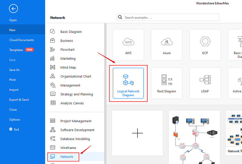
Step 3: Select one logical network diagram template to edit on it or click the [+] sign to start from scratch. Also, you can use massive logical network diagram symbols and elements from libraries in left menu to customize your logical network diagram.

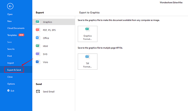
Step 4: Once finished your creation, you can export the file in multiple formats, including Graphics, PDF, editable MS Office file, SVG and Visio vsdx file.
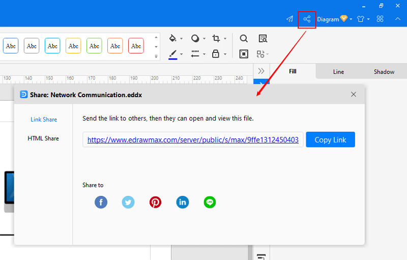
Step 5: Besides, you can share your diagram with others via social media and web page. Or publish your diagram in EdrawMax template gallery to show your work with others.
Part 3: Logical Network Diagram Examples
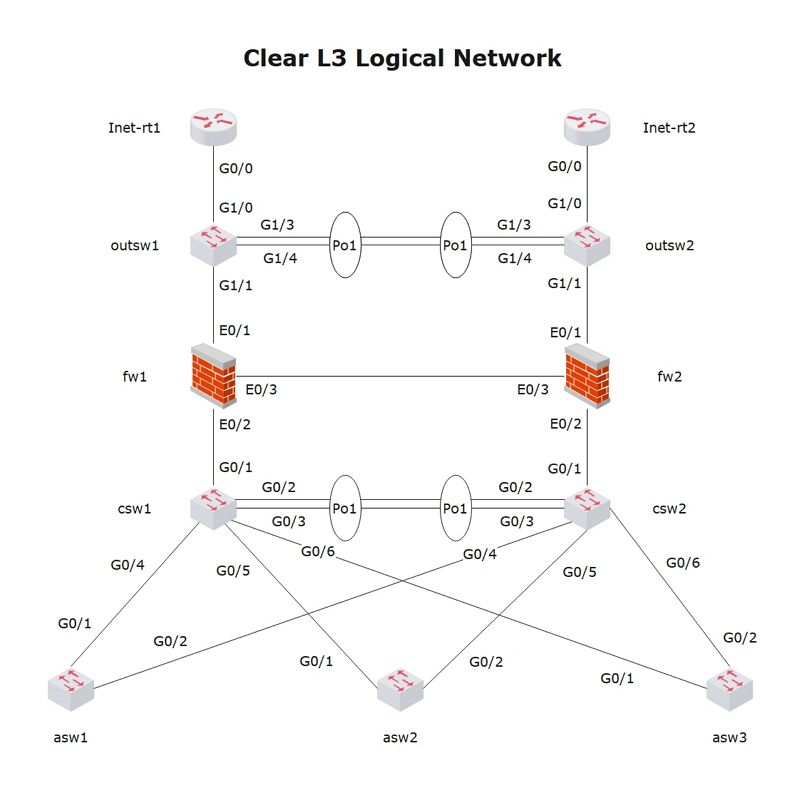
Example1: Clear L3 Logical Network Diagram
This logical network diagram illustrates a simple network layout. The network includes components including Cisco switches, Juniper Netscreen firewalls, and an L2 network diagram along with configurations for most of its devices.
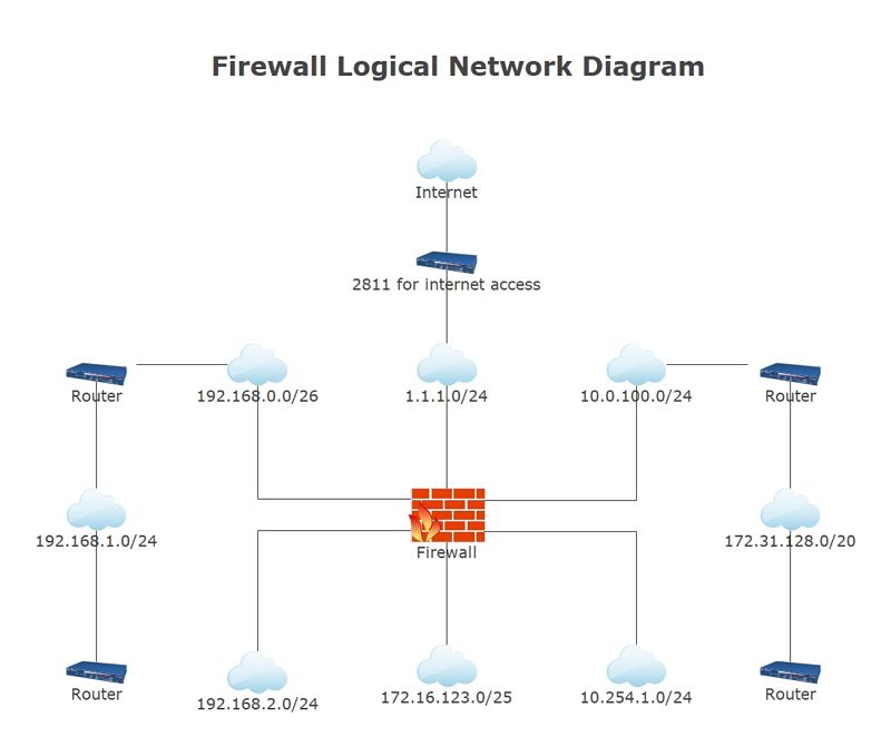
Example2: Firewall Logical Network Diagram
This logical network diagram depicts the flow of information within a network’s components, including network devices, routing protocols, and subnets. IT professionals and network engineers can use a logical network diagram like this to troubleshoot potential problems and optimize networks.

An all-in-one platform for 210+ diagrams.
・ Simple alternative to Visio
・ 26k+ symbols
・ 10K+ free templates
・ 10+ AI diagram generators


Part 4: Conclusion
According to this article, there are mainly three parts to illustrate what is logical network diagram, to tell you how to create logical network diagrams, and to show you some logical network diagram examples.
EdrawMax is an easiest all-in-one diagramming tool, you can create logical network diagrams and any other type diagrams with ease! With substantial logical network diagram symbols and cliparts, designing logical network diagram could be as simple as possible. Also, it supports to export your work in multiple formats and share your work with others. Get started to create your own logical network diagram now!

