Diagram An Ethernet Network
Design Ethernet Network with Edraw
The connectors on the Ethernet shape attach easily to the updated device shapes in Edraw, and they still remain attached, even when you move them.
You can also add text and store network information (such as network names and Internet Protocol (IP) addresses) in your diagram and then extract the information by using one of the three new pre-defined reports.
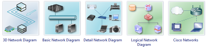
Ethernet Network Symbols
The following symbols are some Ethernet shapes in Edraw. You can drag them from the Edraw Network Library.
Examples of Ethernet LAN Diagram
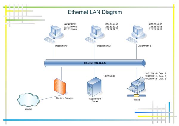
Free Download Network Diagram Software and View All Examples
To use the Ethernet Shape
-
On the File menu, point to Library Gallery, point
to Network, and then click Basic Network Diagram or Detailed Network
Diagram.
Tip: If you want to use the Ethernet shape in another kind of Edraw drawing, open the drawing, and on the File menu, point to Shapes, point to Network, and then click Network and Peripherals.
- From the Network and Peripherals stencil, drag the Ethernet shape onto the drawing page.
- From the Computers and Monitors stencil or Network and Peripherals stencil, drag the network device shapes onto the drawing page.
-
Attach the device shapes to the Ethernet shape by
using each shape's built-in connectors.
How
- Click the Ethernet shape.
-
Rest the pointer over a yellow control handle.
When the pointer changes to a four-headed arrow, drag it to a blue
connection point on one of the device shapes.
When the device shape is correctly connected to the Ethernet shape, the connection point turns red, indicating that it is glued.
Tip: To hide an unused connector, drag its control handle back to the Ethernet shape.
- To add text to a network shape, click the shape and then type. To move the text, drag the yellow control handle.
-
To store data with a shape, right-click the shape,
click Properties, and in the Custom Properties window, type values for the
data you want to store.
After you enter the data, you can generate reports.
How
- On the Tools menu, click Reports.
-
In the Report list, click the name of the
report definition you want to use.
Notes
If you don't see the report definition you're looking for, clear the Show only drawing-specific reports check box, or click Browse and navigate to the location of the report definition.
To modify an existing report definition before generating a report, select the report definition, click Modify, and then follow the instructions in the Report Definition Wizard.
To create a new report definition, click New, and then follow the instructions in the Report Definition Wizard.
-
Click Run, and then in the Run Report dialog
box, select the report format you want.
How
- To save your report as a Web page, click HTML.
- To create your report in a Microsoft Office Excel worksheet, click Excel.
- To save your report as an Excel worksheet embedded in a shape in your drawing, click Edraw shape.
- To save your report as an XML file, click XML.
Note: You must have Microsoft Excel 2000 or later installed to save your report as an Excel worksheet or as an embedded shape in your drawing.
-
Do one of the followings:
-
If you are saving your report as a Edraw
shape on the drawing, select whether to save a copy of the report
definition with the shape or to link to the report definition.
Note: If you plan to share your drawing, select Copy of report definition so that others can see the report.
- If you are saving your report as an HTML or XML file, type a name for the report definition.
-
If you are saving your report as a Edraw
shape on the drawing, select whether to save a copy of the report
definition with the shape or to link to the report definition.
- Click OK.
Tip
- To change the set of colors used in your diagram, Switch to Color Schemes Pane.
The Network and Peripherals stencil also includes a Ring network shape. The Ring network shape works just like the Ethernet shape but represents a ring network.


