SDL Diagram
SDL Definition (Specification and Description Language)
SDL Diagram is widely used to model
state machines in the telecommunications, aviation, automotive and medical
industries. SDL is used to model the details of a system, which can be
simulated and proven, whereas UML is used to model at a higher level of
abstraction.
There are three parts to an SDL diagram: the system definition, block and
process. The system definition defines the major nodes (blocks) of the
system such as clients and servers, while the block charts show more
details. The process diagram shows the processing steps in each block.
SDL Diagram Software
It's easy to create SDL diagrams and business process rapidly with free examples and templates. Create object-oriented diagrams for communications and telecommunications systems and networks, using Specification and Description Language (SDL). Based on CCITT specifications.
Free Download SDL Diagram Software and View All Examples
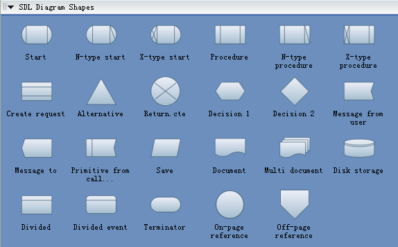
SDL Diagram Symbols
SDL diagrams templates provides you many special shapes, start, variable start, procedure, variable procedure, create request, alternative, return, decision, message from user, message to user, primitive to call, save, document, etc. All these shapes will surely help you draw the SDL diagrams you like.
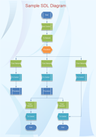
Simple SDL Diagram Example
The following image shows a simple SDL diagram example.