UML Collaboration Diagrams, Free Examples and Software Download
UML Collaboration Diagrams
Use a collaboration diagram (collaboration diagram: An interaction diagram that shows, for one system event described by one use case, how a group of objects collaborates with each other.) to show relationships among object roles such as the set of messages exchanged among the objects to achieve an operation or result.
UML Collaboration diagrams (interaction diagrams) illustrate the relationship and interaction between software objects. They require use cases, system operation contracts, and domain models to exist already. The collaboration diagram demonstrates the transmission of messages between classes and objects (instances). It is created for each system operation that relates to the current development cycle (iteration).
When creating collaboration diagrams, patterns are used to justify relationships. Patterns are the best principles for assigning responsibilities to objects and are described further in the section on patterns. There are two main types of patterns used for assigning responsibilities which are evaluative patterns and driving patterns.
Each system operation initiates a collaboration diagram. Therefore, there is a collaboration diagram for every system operation. Edraw Max is ideal for software designers and software developers who need to draw UML activity diagrams.
How to Create UML Collaboration Diagram
EdrawMax
All-in-One Diagram Software
- Superior file compatibility: Import and export drawings to various file formats, such as Visio
- Cross-platform supported (Windows, Mac, Linux, Web)
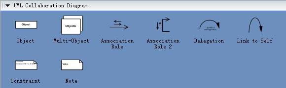
UML Collaboration Diagram Symbols
Edraw Max is an ideal software to draw UML collaboration diagrams.
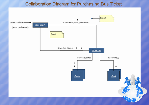
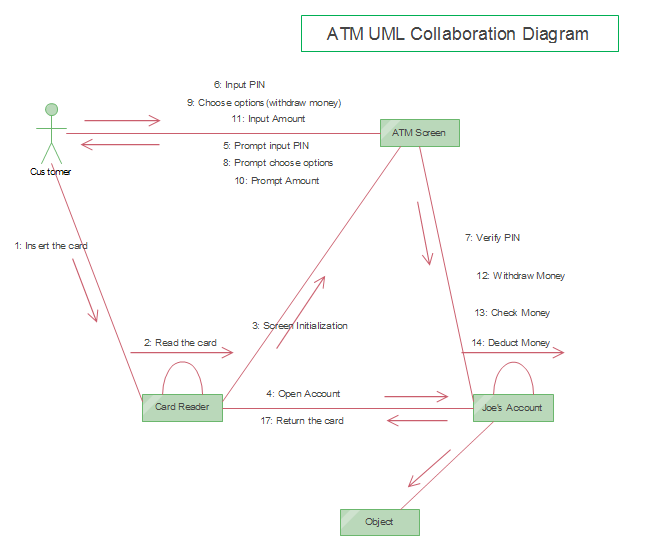
Examples of UML Collaboration Diagram
An UML collaboration diagram example diagram for purchasing a bus ticket.
Another example of UML collaboration showing the structure of ATM program.
Read More:

